
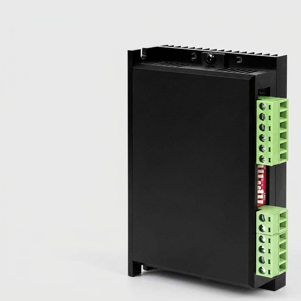
Evaluating SIL3 STO in Micro GaN Servo Drives: A Procurement and Compliance Guide
Evaluate SIL3 STO in micro GaN servo drives globally: compare isolation, CMTI, certification evidence, supplier risks, and RFQ checks. Request review.
As Mobile Autonomous Robots (AMRs), Automated Guided Vehicles (AGVs), and collaborative humanoid platforms shrink in footprint, robotics OEMs are aggressively transitioning to Gallium Nitride (GaN) servo drives. GaN High Electron Mobility Transistors (HEMTs) allow engineers to push switching frequencies to 100kHz, drastically reducing the size of passive components and enabling "micro" drives that fit directly inside robot joints.
However, this miniaturization collides with a non-negotiable physical reality: Functional Safety.
TL;DR (Executive Summary):
- The Paradox: You cannot shrink safety isolation. Achieving SIL3 (Safety Integrity Level 3) / PLe (Performance Level e) Safe Torque Off (STO) requires strict physical creepage and clearance distances that are extremely difficult to fit onto a 40x40mm GaN drive PCB.
- Procurement Trap: Many suppliers market "Micro GaN Drives with STO" but only provide single-channel (non-redundant) STO or require a bulky external safety relay, defeating the space-saving benefits of GaN.
- Decision Boundary: Sourcing a drive with true internal dual-channel SIL3 STO requires validating the supplier's isolation architecture, high dv/dt noise immunity (CMTI), and TÜV/SGS certification status.
(Update: As of Q3 2026, European and North American robotics buyers are increasingly asking drive suppliers to document IEC 61800-5-2 / ISO 13849-1 evidence for true SIL3 or PLe compliance.)
Scope, Assumptions, and Limits
Published for a global audience on July 21, 2026, this guide is written for robotics OEM engineering, sourcing, and compliance teams evaluating 24 V to 80 V DC micro GaN servo drives for AMRs, AGVs, humanoid or cobot joints, and compact frameless-motor actuator modules. Treat it as an RFQ screening and evidence-review framework, not as a certification determination. Final SIL or PL claims must be based on the exact drive SKU, safety architecture, PFHd / MTTFd data, FMEDA, notified-body certificate, wiring, maximum battery or regenerative voltage, pollution degree, enclosure design, and machine-level risk assessment. Values for creepage, CMTI, restart time, and BOM impact are typical engineering screening ranges; require supplier data before production release.
1. The Core Problem: The Physics of STO vs. Miniaturization
Safe Torque Off (STO) is the foundational safety function in modern robotics. Defined by IEC 61800-5-2, STO ensures that no torque-generating energy can continue to act upon a motor. In the event of an emergency stop (E-Stop) or a safety scanner breach, the STO circuit hardware physically disconnects the PWM gate drive signals from the power stage.
Unlike software-based stops, STO must rely on hardware redundancy. To achieve SIL3 (per IEC 61508) or PLe (per ISO 13849-1), the STO circuit must be dual-channel. If one channel fails (e.g., a component short-circuits), the second channel must successfully halt the drive.
The Physical Boundary of Creepage and Clearance
The bottleneck in micro GaN drives is not the logic; it is the physical isolation. Safety standards require absolute galvanic isolation between the low-voltage control logic (where the safety controller sits) and the high-voltage power stage (48V to 60V DC bus for AGVs).
- Clearance: The shortest distance through the air between two conductive parts.
- Creepage: The shortest distance along the surface of the PCB insulating material between two conductive parts.
For a 60V system operating in a polluted industrial environment (Pollution Degree 2 or 3), safety standards typically mandate a creepage distance of at least 1.5mm to 2.0mm across the isolation barrier. When you are designing a micro GaN drive that is only 30mm x 30mm, allocating a continuous 2mm dead-zone across the entire board for safety isolation consumes a massive percentage of the available real estate. It severely limits the routing of signal traces and the placement of thermal vias, creating a massive engineering headache for drive designers.
2. GaN's High dv/dt and The Optocoupler Dilemma
Beyond physical distance, GaN HEMTs present a severe electrical challenge for STO circuits. GaN switches extremely fast—often exceeding 100 V/ns (volts per nanosecond). This high dv/dt generates intense Common-Mode Transient Interference (CMTI).
Historically, drive manufacturers used cheap optocouplers to isolate the STO signals. However, traditional optocouplers have poor CMTI ratings (often < 20 kV/μs). If a GaN drive switching at 100 V/ns couples noise across the isolation barrier, it can falsely trigger the optocoupler, causing parasitic turn-on of the STO circuit—a critical safety failure that could cause a robot arm to jolt during an E-Stop condition.
Moreover, GaN's fast turn-on and turn-off times inherently create ringing if the PCB layout has parasitic inductance. This ringing can couple into the safety logic ground. Digital isolators that utilize capacitive or magnetic coupling (such as those from TI, Silicon Labs, or Analog Devices) are mandatory to prevent this. These isolators feature CMTI ratings exceeding 150 kV/μs. However, these components require a minimum of 8mm of package creepage themselves to satisfy reinforced isolation standards, meaning the component footprint alone is massive relative to a micro GaN board.
3. Visualizing the SIL3 STO Isolation Barrier in GaN Drives
To understand what you are buying, you must understand the board layout. A true SIL3 GaN drive has a distinct "moat" separating the safety logic from the high-voltage switching nodes.
Figure 1: To achieve true SIL3 STO, the PCB must maintain strict creepage limits and use high-CMTI isolators to block GaN switching noise from falsely triggering the safety circuit.
4. Architectural Comparison: How Suppliers Hack "STO"
When a datasheet simply says "Supports STO," procurement teams must immediately ask: What kind of STO? There are several primary architectures that suppliers use to handle STO in low-voltage robotics. Each has vastly different impacts on your Total Cost of Ownership (TCO), robot footprint, MTBF, and overall supply chain risk.
| Architecture | Description | Safety Level | TCO / Footprint Impact | MTBF / Reliability | Procurement Verdict |
|---|---|---|---|---|---|
| 1. True Internal Dual-Channel STO | Redundant STO inputs, high-CMTI isolators, and hardware cross-monitoring directly on a single GaN PCB. | SIL3 / PLe (Certified) | Lowest TCO / Smallest Footprint. No external safety relays needed. Eliminates heavy 48V routing. | High. Fewer cables and connections reduce mechanical failure points in high-vibration AGVs. | Recommended for all OEMs. Demand the TÜV certificate for the specific drive SKU. |
| 2. Networked Safety STO (FSoE) | Dual-channel STO triggered via safety-rated industrial ethernet (e.g., Fail Safe over EtherCAT). | SIL3 / PLe (Certified) | Very Low TCO. Eliminates discrete STO wiring completely. Requires safety PLC on the network. | Highest. Simplifies wiring harness dramatically; diagnostic data is transmitted digitally. | Ideal for complex fleets. Select this if using a central Safety PLC for fleet coordination. |
| 3. Single-Channel Internal STO | Drive features only one STO input. Lacks hardware redundancy and cross-monitoring features. | SIL2 / PLd (At best) | Low Cost, limited compliance. Cannot support heavy automated guided vehicles requiring SIL3. | Moderate. Vulnerable to single-point-of-failure (SPOF) from GaN dv/dt noise breakdown. | Avoid for heavy robotics. Usable only for very low-mass, low-speed service robots. |
| 4. External Safety Relay (Main Power Cut) | Drive has no internal STO. External SIL3 contactor physically cuts the 48V DC bus power to the drive. | SIL3 / PLe (System Level) | High TCO / Massive Footprint. Contactor often larger than the micro drive. Adds ~$50-$150 to BOM. | Lower. Mechanical contactors wear out due to arcing during hard disconnects under load. | The "Phantom Spec" Trap. Destroys the size advantage of buying a micro GaN drive. |
| 5. Software-Only Stop (Disable) | Drive disable command sent via software/network. Not hardware-isolated from the logic controller. | None / Unrated | Zero Cost. Uses existing network or logic pins, but provides no safety guarantees. | Low (Safety Context). Software glitches or MCU lockups can prevent the drive from stopping. | Not acceptable for human-collaborative robots or any machine requiring functional safety. |
| 6. Integrated Safety Controller Drive | Drive includes full SIL3 STO plus Safe Limited Speed (SLS), Safe Brake Control (SBC), and encoder monitoring. | SIL3 / PLe (Advanced) | Highest Initial Cost, best system footprint. Replaces external safety scanners/controllers. | Moderate-High. Highly complex firmware and hardware. Long certification cycles. | Niche/Premium. Choose only if the axis requires complex cinematic safety beyond simple STO. |
5. The "Phantom Specs" Procurement Trap
A common procurement pitfall occurs during the aggressive BOM (Bill of Materials) optimization phase. A buyer or sourcing manager finds a 40x40mm micro GaN drive that costs 20% to 30% less than a slightly larger alternative. The datasheet proudly states: "Compatible with SIL3 Safety Systems."
This is a dangerous marketing trick. In the context of micro drives, "compatible with" usually means the drive lacks internal dual-channel STO completely and relies entirely on Architecture #4 (External Safety Relay).
When the mechanical engineering team attempts to integrate this "cheap, micro" drive into a tight robotic joint space, they encounter a massive roadblock. They realize they must install a bulky, expensive safety contactor to cut the 48V power externally.
- The joint module enclosure must be redesigned and expanded by 30% to fit the contactor.
- The wiring harness becomes significantly more complex and heavy.
- The thermal dynamics change because the relay generates heat.
- The overall cost per axis skyrockets, negating the initial 20% savings on the drive itself.
To prevent this, procurement and engineering teams must aggressively align on evaluating the true, certified boundaries of the servo drive. Do not accept vague datasheet claims. Ask for the block diagram of the STO isolation barrier.
6. Sourcing & Engineering Validation Checklist
Before issuing a Purchase Order (PO) or committing to a long-term supply agreement for a micro GaN servo drive in a safety-critical robotics application, use this detailed checklist to interrogate the supplier and validate the compliance claims:
Hardware Architecture & Certifications
- 1. Dual-Channel Verification: Does the drive have two mathematically and physically independent STO input pins (STO1 and STO2) along with a diagnostic output (STO_STATUS)?
- 2. Independent Certification Status: Is the SIL3 / PLe certification completed by an independent, recognized notified body (e.g., TÜV Rheinland, SGS, UL), or is it merely "designed to meet" SIL3? Request the exact certificate number and verify it against the agency's database.
- 3. PCB Creepage Audit: Can the supplier explicitly state the creepage distance (in millimeters) between the logic/safety zone and the high-voltage GaN power stage? (This should strictly be >1.5mm for a 60V system operating in Pollution Degree 2).
Electrical Integrity & Compatibility
- 4. CMTI Rating Validation: What is the Common-Mode Transient Immunity (CMTI) rating of the STO isolation components? (It must safely exceed the GaN HEMT's maximum dv/dt, typically > 100 kV/μs, preferably > 150 kV/μs).
- 5. External BOM Independence: Does achieving a SIL3 STO rating require adding any external contactors, safety relays, or specialized safety PLCs, or can the drive be directly triggered by standard 24V OSSD (Output Signal Switching Device) signals from a safety laser scanner?
- 6. OSSD Pulse Handling: Does the STO input correctly filter and handle the short test pulses (typically 1ms to 3ms) generated by OSSD safety outputs without accidentally faulting the drive or causing momentary torque loss?
- 7. Maximum STO Voltage Thresholds: Does the STO input accept standard 24V industrial logic directly, or does it require a custom logic-level (5V/3.3V) translation board?
Reliability & Lifecycle Documentation
- 8. Reliability Metrics (MTBF/PFHd): Has the supplier provided the exact Mean Time Between Failures (MTBF) and the Probability of Dangerous Failure per Hour (PFHd) for the internal STO circuit? (These numbers are required for your system-level safety calculations).
- 9. Supply Chain Transparency: Are the critical isolation components (e.g., the digital isolators) multi-sourced, or does the drive rely on a single-source custom ASIC that could create a supply chain bottleneck?
- 10. Failure Mode Effects and Diagnostic Analysis (FMEDA): Can the supplier provide an FMEDA report detailing how the drive's STO circuit behaves under specific component failure scenarios?
7. The Impact on TCO for Fleet Operations
For procurement teams and operations managers overseeing fleets of 500+ Automated Guided Vehicles (AGVs) or AMRs, the financial impact of the chosen STO architecture scales dramatically.
Consider a standard 4-axis AGV used in a heavy-duty warehouse environment.
If you choose drives with External Safety Relays (Architecture 4), you must route thick, heavy 48V power cables through the mechanical safety contactor. This contactor wears out mechanically after roughly 100,000 to 1,000,000 actuation cycles. In a busy warehouse where E-Stops and zone breaches happen daily, those cycles add up quickly. When a contactor fails, the AGV requires manual maintenance downtime. Furthermore, the massive size of these contactors forces the AGV chassis to be larger and heavier, which directly reduces the payload-to-weight ratio and lowers the overall battery efficiency of the vehicle.
Conversely, if you deploy drives featuring True Internal Dual-Channel STO (Architecture 1), the safety mechanism is entirely solid-state. The STO inputs draw only milliamperes of current at 24V. There are absolutely no mechanical contacts to wear out, spark, or arc. The wiring harness becomes significantly thinner, lighter, and more flexible, which drastically reduces cable fatigue in moving joints. The robotic joint module remains hermetically sealed without needing excess internal volume for mechanical relays.
While the initial unit cost of a certified true dual-channel micro GaN drive might be $30 to $50 higher, the elimination of the external safety relay, the reduction in wiring harness complexity, the saved labor during assembly, and the massive reduction in maintenance downtime yields a drastically lower Total Cost of Ownership (TCO) across a 5-year to 7-year fleet lifecycle. This is the true value of integrated functional safety.
8. Common Failure Modes and Mitigation Strategies
When implementing SIL3 STO in high-frequency GaN environments, engineering teams must be vigilant regarding several critical failure modes that can compromise safety.
1. Parasitic Inductance and Ground Bounce
GaN HEMTs switch so quickly that even minor parasitic inductance in the PCB layout can cause severe ground bounce. If the safety logic ground is not perfectly isolated and stable relative to the power ground, this bounce can be interpreted by the microcontroller or safety monitor as a false STO signal. Mitigation: Ensure the drive supplier utilizes a strict split-ground plane design with isolated power supplies for the safety sector.
2. Optocoupler Degradation
If a supplier attempts to cut costs by using standard optocouplers instead of high-CMTI capacitive or magnetic isolators, the LED inside the optocoupler will degrade over time, especially in high-temperature environments (like the inside of a sealed robotic joint). This degradation reduces the Current Transfer Ratio (CTR), eventually causing the STO circuit to fail or become hyper-sensitive to noise. Mitigation: Mandate digital isolators with a defined CMTI >150 kV/μs and zero reliance on opto-emissive degradation.
3. OSSD Test Pulse Sensitivity
Safety scanners constantly send tiny, millisecond-long test pulses (dropping the 24V signal to 0V momentarily) to verify the integrity of the safety wiring. If the servo drive's STO circuit reacts too quickly and lacks a proper digital filter, these test pulses will cause the drive to instantly drop torque for a millisecond, causing the robot arm to judder or the AGV to vibrate continuously. Mitigation: Verify that the drive's firmware and STO hardware include an OSSD filter that ignores low-state pulses under 3ms.
9. FAQ: Evaluating STO in GaN Drives
Q: Can we achieve SIL3 certification by putting two single-channel STO drives in parallel? A: Absolutely not. Functional safety standards require redundancy to stop each specific identified hazard. If a specific robotic joint motor must stop safely to prevent injury, the drive controlling that specific motor must inherently possess dual-channel redundancy. Paralleling two different drives that control two completely different motors does not solve the single-point-of-failure (SPOF) risk for the first motor.
Q: Why do GaN drives struggle with STO isolation more than traditional Silicon MOSFET drives? A: Traditional Silicon MOSFETs switch relatively slowly (lower dv/dt), which generates significantly less high-frequency transient noise. Because of this, standard, low-cost optocouplers are usually sufficient to isolate the STO signal in older silicon-based drives. However, GaN switches an order of magnitude faster (often exceeding 100 V/ns). This high dv/dt environment demands high-CMTI digital isolators, which consume considerably more PCB real estate to maintain required creepage distances. Fitting these larger components onto a 30x30mm or 40x40mm board is an immense layout challenge.
Q: If we just cut the 48V main power via a contactor instead of using STO, isn't that mathematically just as safe? A: Cutting main power (Safe Torque Off via power removal) achieves the safety goal, but it creates massive operational inefficiencies. When you physically cut the 48V power, the drive's internal microcontroller completely loses power. When power is restored after the safety event is cleared, the drive must run a full boot sequence, re-initialize the encoder, clear software faults, and re-establish network communication (e.g., EtherCAT or CANopen). This boot process can take 2 to 5 seconds. True STO, on the other hand, only severs the power to the motor's gate drivers, leaving the logic processor and network active. This allows for an instantaneous restart (under 10 milliseconds) the moment the safety zone is deemed clear.
Q: Our robot operates on a 24V battery system instead of 48V or 60V. Do the strict creepage rules still apply to us? A: Yes, they do, although the legally required absolute distances might be fractionally smaller. However, most stringent industrial safety audits will classify your system based on the maximum possible charging voltage or the peak regenerative braking voltage, rather than the nominal battery voltage. This often pushes a nominal 24V system into a higher voltage classification, mandating the same strict creepage rules as a 48V system.
Q: Does STO safely stop a robot arm from dropping due to gravity? A: No. STO only removes active torque-generating power from the motor. It does not actively apply brakes. For vertical axes or arms that could collapse under gravity, you must implement Safe Brake Control (SBC) alongside STO, which requires a separate safety-rated channel to engage a mechanical holding brake the moment STO is triggered.
10. Conclusion & Next Steps for Robotics OEMs
The aggressive drive toward miniaturization in robotics must never come at the expense of functional safety and international compliance. As procurement teams, sourcing directors, and engineering managers evaluate the next generation of micro GaN servo drives, they must look far beyond the basic dimensions and peak current ratings printed on the front page of the datasheet.
A micro drive is only truly "micro" if it contains all the necessary compliance features internally. Forcing an external safety relay onto the BOM is a hidden cost that engineering teams will inevitably pay in expanded footprint, increased weight, higher assembly complexity, and reduced mechanical reliability. To build a robust, future-proof AGV, AMR, or humanoid platform that can pass European and North American safety audits, OEMs must mandate dual-channel STO at the bare PCB level.
Ready to evaluate a true SIL3 GaN architecture for your robotic joints? Our application engineering team can review your creepage, CMTI, STO evidence, and PFHd documentation requirements against the realities of compact robot-joint packaging. Explore our GaN Low-Voltage Servo Drives or contact our dedicated application engineering team for a Custom OEM Solution to review the relevant STO implementation, block diagrams, and reliability data during your RFQ process.
Sources & References
- IEC 61800-5-2:2016 - Adjustable speed electrical power drive systems - Part 5-2: Safety requirements - Functional.
- ISO 13849-1:2023 - Safety of machinery — Safety-related parts of control systems.
- Texas Instruments: High-voltage reinforced isolation - Understanding creepage, clearance, and CMTI in high dv/dt wide-bandgap designs.
- TÜV Rheinland: Functional Safety Product Certification - Overview of functional safety certification for industrial automation.
Author

Categories
More Posts
GaN vs Silicon MOSFETs in Low-Voltage Servo Drives: Thermal & Power Density Compared
How to Specify 48V GaN Servo Drives for Low-Inductance Motors: Eliminating Chokes and Current Ripple
Specify 48V GaN servo drives for low-inductance robotics motors: current ripple limits, choke elimination, EMI risks, RFQ checks, and sourcing trade-offs.
Frameless Motor Integration: Sourcing Guide for Hollow Shaft Servo Drives