
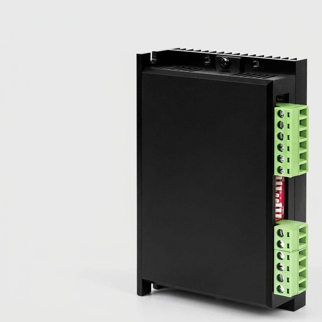
How to Specify 48V GaN Servo Drives for Low-Inductance Motors: Eliminating Chokes and Current Ripple
Specify 48V GaN servo drives for low-inductance robotics motors: current ripple limits, choke elimination, EMI risks, RFQ checks, and sourcing trade-offs.
When engineering teams design next-generation robotics—such as surgical manipulators, aerospace actuators, and dynamic humanoid joints—they consistently gravitate toward low-inductance motors. Coreless, slotless, and high-pole-count Brushless DC (BLDC) motors offer unparalleled acceleration, zero cogging torque, and exceptional power density.
However, when procurement teams source standard 48V silicon-based servo drives to run these advanced motors, the project often hits a brick wall. The fundamental electrical mismatch between a standard 20kHz silicon drive and a low-inductance motor results in massive current ripple, catastrophic overheating, and reduced battery life.
TL;DR (Executive Summary):
- The Problem: Low-inductance motors driven by legacy 20kHz PWM drives suffer from extreme current ripple, generating excessive heat and necessitating bulky, expensive external inductor chokes.
- The Solution: Gallium Nitride (GaN) servo drives operate at high switching frequencies (100kHz to 200kHz+), natively reducing current ripple and eliminating the need for external chokes.
- Sourcing Impact: While the upfront cost of a GaN drive may be marginally higher, the Total Cost of Ownership (TCO) is lower when accounting for the elimination of external filters, reduced heatsink requirements, and extended battery life.
This comprehensive guide bridges the gap between engineering requirements and procurement strategy, detailing exactly how and why to specify high-frequency GaN servo drives for low-inductance applications.
Scope note: Prepared July 23, 2026 for global robotics OEM engineering and sourcing teams evaluating 24V to 60V DC servo platforms, especially 48V battery-powered joints, AGVs/AMRs, compact cobots, and medical or aerospace actuators using low-inductance BLDC, slotless, or coreless motors. Treat the numbers below as RFQ-screening and prototype-planning ranges, not a substitute for final motor thermal testing, EMC certification, or safety approval on the assembled machine. Results depend on motor inductance and resistance, bus voltage, PWM frequency, cable length, current-loop bandwidth, cooling boundary, and firmware settings.
The Physics of the Problem: Inductance, Current Ripple, and Heat
To understand why traditional drives fail with modern high-performance motors, we must look at the basic physics of a motor coil. A motor's inductance (L) acts as an electrical flywheel, smoothing out the pulses of voltage sent by the servo drive's Pulse Width Modulation (PWM).
The rate of change of current in the motor phases is governed by the equation:
di/dt = V / L
Where:
Vis the DC bus voltage (e.g., 48V).Lis the motor's phase-to-phase inductance.
In traditional industrial servomotors, inductance is relatively high (often several millihenries, mH). Therefore, even if the drive pulses the voltage at a standard 10kHz or 20kHz, the current rises slowly, resulting in a smooth sine wave.
However, high-performance slotless or coreless motors have extremely low inductance, often in the range of 10 to 100 microhenries. When a 48V bus is applied to a 50 microhenry motor at 20kHz, the current spikes violently before the drive can switch off. This creates a massive current ripple.
The Consequences of High Current Ripple
I^2RCopper Losses: Current ripple does not produce useful torque; it only produces heat. The RMS value of the current increases dramatically, causing the motor windings to overheat even at standstill.- Eddy Current Iron Losses: The high-frequency magnetic flux variations induce eddy currents in the motor's stator, causing further thermal degradation.
- Control Instability: The jagged current waveform makes it incredibly difficult for the drive's current loop to measure and control torque accurately, leading to audible whining and mechanical vibration.
The Legacy Solution: External Inductor Chokes
When faced with a low-inductance motor overheating on a 20kHz drive, engineers traditionally apply a brute-force solution: External Inductor Chokes. By wiring three heavy copper coils in series between the drive and the motor, they artificially increase the system's inductance.
From a procurement and system integration perspective, this is a disaster:
- Weight and Volume: A 3-phase LC filter or choke block is often larger and heavier than the servo drive itself. In weight-critical applications like drones or robotic arms, this entirely defeats the purpose of buying a lightweight coreless motor.
- Cost: High-current, low-resistance inductors are expensive, adding hidden BOM (Bill of Materials) costs.
- Efficiency: The chokes have their own internal resistance, bleeding away battery power as heat.
- Wiring Complexity: Adding external components introduces more points of failure, more connectors, and more labor during assembly.
The GaN Advantage: 100kHz+ Switching Frequencies
The elegant solution to the low-inductance problem is not to add external inductance, but to switch the voltage faster. If the PWM frequency is increased from 20kHz to 100kHz, the "on" time of each pulse is divided by five. The current has much less time to rise, meaning the current ripple is proportionally reduced by a factor of five.
Why didn't we always do this? Switching Losses. Traditional Silicon (Si) MOSFETs suffer from high switching losses. Every time the transistor turns on or off, it passes through a resistive state, generating heat. If you attempt to switch a standard silicon servo drive at 100kHz, the drive itself will overheat and burn out.
Gallium Nitride (GaN) is a Wide Bandgap (WBG) semiconductor material that fundamentally changes this limitation. GaN transistors have exceptionally low gate charge and zero reverse recovery charge, allowing them to turn on and off almost instantaneously. This enables servo drives to operate comfortably at 100kHz, 200kHz, or even higher, with lower switching losses than a silicon drive running at 20kHz.
By switching at 100kHz, the GaN drive provides a remarkably smooth current waveform. The motor runs cooler, vibration is eliminated, and the bulky external choke can be completely removed from the BOM.
Architectural Comparison: Silicon vs. GaN for Low-Inductance Systems
When evaluating the architecture for a robotic joint or actuator utilizing a low-inductance motor (below 100 microhenries), cross-functional teams must weigh the system-level impacts. The table below outlines the critical differences.
| Specification / Parameter | Legacy Silicon (Si) Architecture | Next-Gen Gallium Nitride (GaN) Architecture | Sourcing Impact |
|---|---|---|---|
| Max PWM Frequency | 20kHz - 30kHz | 100kHz - 200kHz+ | GaN uniquely enables ultra-high frequency operation without thermal failure. |
| Current Ripple in Motor | High (Often >30% of rated current) | Extremely Low (below 5% of rated current) | GaN prevents motor overheating and extends the lifespan of the winding insulation. |
| External Choke Required? | Yes (Adds weight, cost, volume) | No (Direct drive to motor) | Major BOM reduction; GaN eliminates heavy copper inductors and simplifies wiring. |
| Current Loop Bandwidth | ~1kHz - 2kHz | ~4kHz - 10kHz+ | GaN provides vastly superior dynamic response, critical for precision cobots and CNCs. |
| Dead-Time Requirements | 500ns - 1000ns | 10ns - 50ns | GaN minimizes zero-crossing distortion, resulting in smoother low-speed motion. |
Switching Edge Slew Rate (dV/dt) | Low to Moderate (~10 V/ns) | Extremely High (up to 100 V/ns) | Risk Factor: GaN requires careful EMI management and high-quality shielded motor cables. |
| Drive Thermal Footprint | Requires large aluminum heatsink | PCB can often dissipate heat natively | GaN enables ultra-compact, integrated "in-wheel" or frameless joint designs. |
Total Cost of Ownership (TCO) & Procurement Strategy
For a procurement manager, a GaN servo drive might appear 15% to 30% more expensive on a pure component-to-component price comparison against a legacy silicon drive. However, assessing the Total Cost of Ownership (TCO) reveals a different reality:
- Elimination of the LC Filter: An industrial-grade 3-phase choke for a 48V/20A system can cost between $30 and $80, completely negating the price advantage of the cheaper silicon drive.
- Reduced Mechanical Overhead: Without the need to mount and house bulky chokes and massive drive heatsinks, the mechanical enclosures can be drastically smaller and cheaper to machine.
- Battery Optimization: In mobile robotics (AGVs/AMRs/Humanoids), battery capacity is a major cost driver. The combination of eliminated choke resistance and reduced motor copper losses translates directly to extended battery life, allowing procurement to specify a smaller, cheaper battery pack for the same run-time.
- Assembly and Logistics: Fewer components mean fewer connectors, reduced manual wiring time, lower shipping weights, and a simplified supply chain with fewer points of failure.
Sourcing & Engineering Validation Checklist
When your team is transitioning to GaN servo drives for low-inductance applications, use this collaborative checklist to ensure supplier readiness and technical compatibility:
- Verify Motor Inductance: Confirm with your motor supplier (e.g., Maxon, Portescap) that the phase-to-phase inductance is low enough to warrant high-frequency driving (typically under 200 microhenries).
- Demand PWM Flexibility: Ensure the sourced GaN drive allows the PWM frequency to be software-configured (e.g., adjustable from 40kHz to 150kHz) so engineers can tune the exact frequency to the motor's sweet spot.
- Check Dead-Time Compensation: Ask the supplier for their dead-time specifications. GaN's advantage is wasted if the drive's firmware still enforces legacy 500ns dead-times, which causes harmonic distortion. Look for dead-times under 50ns.
- Evaluate EMI Certifications: Because GaN switches rapidly (high
dV/dt), it generates high-frequency noise. Request pre-compliance reports for CISPR 11 / EN 55011 (Radiated and Conducted Emissions) from the drive manufacturer. - Review Controller Bandwidth: A high PWM frequency should be paired with a high-speed microcontroller. Confirm that the current loop update rate is at least equivalent to the PWM frequency (e.g., a 100kHz PWM should have a 100kHz current loop).
- Confirm Communication Protocols: Ensure the drive supports the required deterministic bus (e.g., EtherCAT DC Sync0 or CAN FD) with verified ESI files and cycle-time evidence.
Managing the Trade-offs: EMI and dV/dt
It is critical to acknowledge that GaN technology is not without its engineering challenges. The very feature that makes GaN efficient—its incredibly fast switching speed—results in high voltage slew rates (dV/dt).
When voltage transitions from 0V to 48V in a matter of nanoseconds, it creates high-frequency electromagnetic interference (EMI). If left unmanaged, this EMI can couple into encoder cables, causing position errors, or radiate outward, failing CE/FCC certifications.
How to mitigate this:
- Short Cable Runs: GaN drives are ideally suited for decentralized architectures. By mounting the drive directly onto the back of the motor (integrated servo), the phase wires are kept to a few centimeters, trapping the EMI before it can radiate.
- Active Gate Driving: Top-tier drive manufacturers tune the gate resistors on the GaN transistors to slightly soften the switching edge. This trades a tiny fraction of efficiency for a massive reduction in EMI.
- Shielding: Mandate double-shielded cables for all logic and encoder feedback lines routed near the power stage.
Application Boundaries: When NOT to Specify GaN
To maintain engineering integrity, it is important to recognize where GaN does not add value.
Do not specify a high-frequency GaN drive if:
- You are driving a traditional, heavy NEMA 34 stepper motor or a massive AC induction motor. These motors have very high inductance (often in the
mHrange) and naturally filter 10kHz to 20kHz PWM without issue. - Space and weight are entirely unconstrained (e.g., a stationary factory conveyor belt wired back to a massive centralized electrical cabinet). In these scenarios, legacy silicon IGBTs or MOSFETs remain the most cost-effective solution.
Frequently Asked Questions (FAQ)
1. Will running a GaN drive at 100kHz degrade the motor's insulation?
While GaN features high dV/dt, 48V bus voltages are well within the dielectric breakdown limits of standard motor winding enamel. Insulation degradation from dV/dt is primarily a concern in high-voltage (400V - 800V) systems, not low-voltage 48V robotics.
2. Do we still need a heat sink for a GaN drive?
It depends on the continuous current. Because GaN is highly efficient, drives operating under 10A RMS can often rely purely on the PCB copper and ambient convection. For higher currents (20A+), thermally bonding the drive to the robot's aluminum chassis is highly recommended.
3. Can a GaN drive interface with our existing legacy PLC?
Yes. The power stage (GaN) is completely decoupled from the logic stage. A modern GaN drive supports standard industrial protocols like EtherCAT, PROFINET, or CANopen, making it entirely transparent to the master PLC.
4. What happens if we run a low-inductance motor on a 20kHz Si drive without a choke?
The extreme current ripple will cause rapid, severe overheating. The motor's stator will likely reach its thermal limit within minutes, and the continuous high RMS current may trip the drive's overcurrent protection or melt the winding insulation.
5. Are GaN components subject to supply chain shortages?
While GaN is newer than Silicon, major foundries (like TSMC and EPC) have rapidly scaled production capacity. Securing drives from vendors who utilize dual-layout PCB designs can further mitigate specific IC shortages.
Conclusion
The transition to low-inductance, high-performance motors in modern robotics necessitates a paradigm shift in how we source servo drives. Attempting to force-fit legacy 20kHz silicon drives into these applications results in compromised thermal performance, wasted battery life, and the heavy burden of external chokes.
By specifying high-frequency GaN servo drives, engineering and procurement teams can collaboratively achieve a "positive weight-reduction spiral"—eliminating chokes, shrinking heatsinks, extending battery life, and ultimately lowering the Total Cost of Ownership for the robotic system.
Next Steps: Ready to eliminate chokes from your BOM? Explore our GaN Low-Voltage Servo Drives for compact 48V robotics platforms, or Contact Our Engineering Team to discuss integrating GaN technology directly into your custom joint modules.
References & Sources
- Texas Instruments: High-frequency motor drive design using GaN - Detailing the efficiency gains of wide bandgap devices in motor control.
- Infineon Technologies: Motor control with GaN systems - Analyzing current ripple reduction and acoustic noise elimination.
- Texas Instruments: Gallium nitride power management overview - Summarizing GaN switching-loss, power-density, and efficiency advantages relevant to compact motor-drive hardware.
Author

dV/dtApplication Boundaries: When NOT to Specify GaNFrequently Asked Questions (FAQ)1. Will running a GaN drive at 100kHz degrade the motor's insulation?2. Do we still need a heat sink for a GaN drive?3. Can a GaN drive interface with our existing legacy PLC?4. What happens if we run a low-inductance motor on a 20kHz Si drive without a choke?5. Are GaN components subject to supply chain shortages?ConclusionReferences & SourcesMore Posts
How to Select a 48V EtherCAT Servo Drive for Humanoid Robot Joints
Sourcing Decentralized IP67 GaN Servo Drives: Wiring Cost Reduction and Thermal Trade-offs
Global sourcing guide for decentralized IP67 GaN servo drives, covering wiring cost models, thermal derating limits, RFQ evidence, and OEM sourcing CTAs.
GaN vs Silicon MOSFETs in Low-Voltage Servo Drives: Thermal & Power Density Compared