
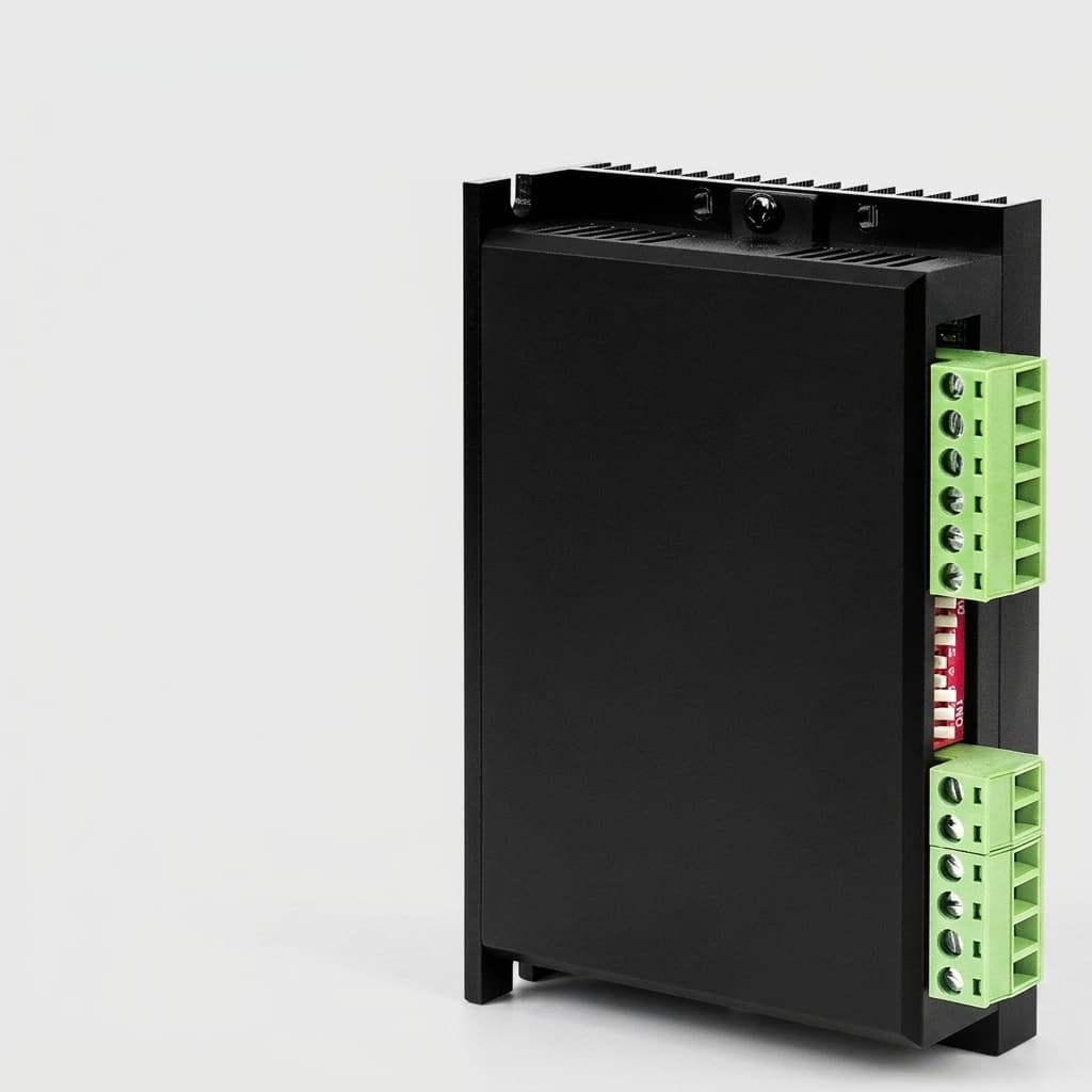
EMI Mitigation & Compliance for High-Frequency GaN Servo Drives in Robotics
GaN servo drive EMI mitigation guide for robotics: compare dV/dt tuning, filters, shielding, EMC risks, and RFQ checks before sourcing. Request review.
The transition from traditional Silicon (Si) to Gallium Nitride (GaN) in low-voltage servo drives has unlocked unprecedented levels of power density and efficiency. For robotics OEMs building autonomous mobile robots (AMRs), automated guided vehicles (AGVs), and untethered humanoids, the ability to shrink the footprint of a joint actuator while reducing thermal output is a game-changer. However, this leap in performance comes with a significant engineering trade-off: severe Electromagnetic Interference (EMI) challenges driven by extreme $dV/dt$ slew rates.
In this comprehensive guide, we explore the physics behind GaN-induced EMI, its impact on robotic systems and motor longevity, and the critical mitigation strategies that both engineers and procurement teams must evaluate when sourcing next-generation servo drives.
TL;DR (Executive Summary):
- The Core Issue: GaN transistors can switch in mere nanoseconds, resulting in voltage slew rates ($dV/dt$) exceeding 100 V/ns. This high-frequency action generates significant conducted and radiated EMI, which can disrupt sensitive sensors (LIDAR, encoders, cameras) and cause compliance failures (CE/FCC).
- Mitigation Approaches: Solving GaN EMI requires a holistic approach, including active gate drive tuning, optimized low-parasitic PCB layouts, localized shielding, and appropriate passive output filtering.
- Sourcing Impact: Procurement teams cannot assume a GaN drive is "plug-and-play." Selecting a vendor requires verifying their EMI test reports, understanding their layout expertise, and ensuring the drive will not degrade the lifespan of low-inductance frameless motors.
Scope, Assumptions, and Limits
This guide was prepared for global robotics OEM engineering and sourcing teams evaluating low-voltage GaN servo drives, typically 24 V to 80 V DC bus platforms used in AMRs, AGVs, humanoid joints, cobots, and compact frameless-motor actuators. The recommendations are not a substitute for final EMC certification on the assembled robot, and they do not cover medium-voltage industrial drives, medical safety certification, or site-specific radio approvals. Treat the $dV/dt$, filter, and shielding guidance as an RFQ screening framework: final limits depend on bus voltage, motor inductance, cable length, enclosure bonding, PCB layout, firmware settings, and the compliance standard selected for your target market.
1. Understanding the Physics: $dV/dt$ and High-Frequency Ringing
To understand why GaN creates EMI, we must look at the switching edge. A power transistor acts as a switch, rapidly connecting and disconnecting the DC bus voltage to the motor phases to synthesize an AC waveform (Pulse Width Modulation, or PWM).
Traditional Silicon MOSFETs switch relatively slowly. Their voltage transitions ($dV/dt$) typically hover around 5 to 10 V/ns. In contrast, GaN High Electron Mobility Transistors (HEMTs) lack a reverse-recovery charge and possess much lower gate capacitance, allowing them to turn on and off almost instantaneously. It is common to see GaN devices exhibiting slew rates of 50 V/ns, 100 V/ns, or even higher.
While this near-instantaneous switching dramatically reduces switching losses (the heat generated during the transition), it introduces high-frequency harmonics. According to Fourier analysis, the faster the rising or falling edge of a pulse, the higher the frequency content of the resulting spectrum. This high-frequency energy couples through parasitic capacitances within the PCB, the motor cables, and the motor itself, transforming the entire robotic chassis into an unintended antenna.
Visualizing the Switching Edge and Noise Generation
As illustrated above, the GaN switching edge induces a severe overshoot and ringing phenomenon when interacting with the stray inductance of the PCB traces. This high-frequency ringing is the primary source of radiated emissions.
2. The Hidden Cost of EMI in Mobile Robotics
Why does EMI matter so much in modern robotics? Unlike a heavy industrial pump located in a steel enclosure, a modern AMR or humanoid robot is a densely packed ecosystem of power electronics, sensitive digital sensors, and wireless communication modules.
- Sensor Degradation and Data Corruption: High-frequency noise can couple into adjacent low-voltage data lines. Encoders (absolute or incremental) are particularly vulnerable; a corrupted encoder packet can cause the drive to calculate incorrect commutation angles, leading to sudden jerks, overcurrent faults, or catastrophic runaway conditions. Similarly, noise injected into LiDAR or camera interfaces can compromise the robot's navigation and safety systems.
- Regulatory Compliance (CE/FCC/CISPR): Entering the European or North American markets requires strict adherence to electromagnetic compatibility (EMC) standards. A robot that radiates excessive EMI will fail CE marking (e.g., EN 61000-6-4 for industrial environments). Failing EMC testing late in the product development cycle often forces a complete and costly redesign of the power architecture.
- Wireless Communication Dropout: Autonomous robots rely on Wi-Fi (2.4 GHz / 5 GHz), Bluetooth, or 5G for fleet management and telemetry. The broadband noise generated by unmitigated GaN switching can raise the noise floor, severely degrading the signal-to-noise ratio (SNR) of onboard wireless modules, leading to dropped connections and stalled fleets.
3. The Threat to Motor Insulation and Bearings
Beyond electronic interference, extreme $dV/dt$ poses a physical threat to the motor itself. When a fast voltage pulse travels down a motor cable, impedance mismatches between the cable and the motor windings cause the voltage wave to reflect.
In systems with longer cables, this reflection can cause the voltage at the motor terminals to double (e.g., a 48V bus spikes to 96V, or an 80V bus spikes to 160V). While this may seem low compared to high-voltage grid systems, the steep edge of the pulse stresses the inter-turn insulation of the motor windings. Over millions of cycles, this localized dielectric stress can lead to premature insulation breakdown and short circuits.
Furthermore, high $dV/dt$ induces common-mode currents that find their way to earth ground through the path of least resistance. Often, this path is through the motor shaft and bearings. When the induced voltage across the bearing lubricant film exceeds its dielectric breakdown threshold, electrical discharge machining (EDM) occurs. This continuous micro-arcing pits the bearing races, leading to mechanical vibration, audible whining, and eventually, catastrophic mechanical failure of the joint.
4. Core Mitigation Strategies: Engineering Solutions
Effectively taming GaN EMI is not achieved with a single "silver bullet." It requires a multi-layered engineering approach. When evaluating a supplier's GaN drive, you should look for the implementation of the following techniques.
A. Gate Drive Tuning (Active Mitigation)
The most direct way to reduce $dV/dt$ is to slow down the turn-on and turn-off of the GaN HEMT. This is typically achieved by increasing the gate resistance ($R_g$) in the driver circuit.
While increasing $R_g$ lowers the slew rate and dramatically reduces high-frequency ringing, it directly contradicts the primary reason for using GaN: low switching losses. Engineers must find the optimal "sweet spot" where the slew rate is slow enough to meet EMI regulations but fast enough to maintain acceptable thermal performance within the joint cavity. Advanced active gate drivers (AGDs) can dynamically shape the gate current during the switching event, suppressing overshoot without heavily sacrificing efficiency, though they add cost and complexity to the BOM.
B. Minimized Parasitic Inductance (Layout Mitigation)
In GaN design, PCB layout is paramount. Even a few nanohenries (nH) of stray inductance in the power commutation loop will resonate with the GaN device's output capacitance ($C_oss$), causing massive voltage ringing.
Top-tier GaN servo drives utilize specialized PCB stack-ups, keeping the high-frequency power loop extremely tight. They deploy local DC-link decoupling capacitors (often low-ESL ceramic capacitors) mere millimeters from the GaN HEMTs. If a vendor's PCB layout routes power traces loosely over long distances, the drive will invariably fail EMC testing, regardless of other mitigations.
C. Output Filtering (Passive Mitigation)
When modifying the switching edge is insufficient or undesirable, passive output filters are required between the drive and the motor.
- $dV/dt$ Reactors (Chokes): Small inductive components added to the motor phases. They slightly extend the rise time of the voltage pulses arriving at the motor, reducing insulation stress and common-mode bearing currents.
- Sine Wave Filters: An LC filter network that converts the harsh PWM square waves into smooth sinusoidal voltage waveforms. While extremely effective at eliminating high-frequency EMI and motor stress, they are bulky, heavy, and expensive—often negating the size and weight benefits of choosing GaN in the first place.
- Common-Mode Chokes (Ferrite Cores): Placing ferrite cores around the three motor phase wires together absorbs common-mode noise. This is a common, cost-effective retrofitting technique used in robotics, though it takes up physical space within the robotic arm.
D. System-Level Grounding and Shielding
Radiated EMI can be contained through proper enclosure design. The servo drive should ideally be housed in an aluminum or conductive casing that is bonded to the robot's equipotential grounding system via low-impedance braided straps.
Furthermore, integrating the motor drive directly onto the back of the frameless motor (Integrated Motor Drive, or IMD architecture) virtually eliminates motor cables. Since motor cables act as the primary transmitting antennas for PWM noise, removing them drastically reduces radiated emissions and eliminates transmission line reflection issues.
5. Comparative Trade-off Matrix: EMI Mitigation Techniques
For engineering and procurement teams deciding how to tackle GaN EMI, the following matrix breaks down the trade-offs of each mitigation strategy.
| Mitigation Technique | Primary Benefit for System | Negative Trade-offs (Cost / SWaP / Heat) | Recommended Application Scenario | Effectiveness (Conducted EMI) | Effectiveness (Radiated EMI) |
|---|---|---|---|---|---|
| Increase Gate Resistor ($R_g$) | Virtually zero cost; simple to implement via BOM change. | Increases switching losses; generates more heat; negates some GaN benefits. | Cost-sensitive AGVs with adequate thermal sinking. | Moderate | High |
| Optimized PCB Power Loop | Solves the root cause of ringing without adding component cost or heat. | Requires highly experienced RF/Power design engineers; strict layout rules. | Universal requirement for all GaN drives. | High | High |
| Common-Mode Ferrite Chokes | Easy to add later; cheap; effectively reduces common-mode bearing currents. | Consumes physical space in tight joints; adds minor weight. | Retrofitting robotic arms struggling with encoder noise. | High | Moderate |
| Output Sine Wave Filter (LC) | Cleans waveform completely; eliminates motor insulation stress and EDM. | Very bulky, heavy, and expensive; induces voltage drops. | Sensitive medical robotics; extremely long cable runs. | Very High | Very High |
| Integrated Motor Drive (IMD) | Eliminates motor cables (the antennas); maximizes spatial efficiency. | Custom mechanical integration required; concentrates heat at the motor. | Humanoids, exoskeletons, and highly compact robot joints. | High | Very High |
| Active Gate Drivers (AGD) | Precision control over overshoot without massive thermal penalties. | High component cost; requires complex control circuitry. | Premium aerospace and defense robotics. | Moderate | High |
6. Sourcing & Procurement: Vendor Evaluation Checklist
Procuring a GaN-based servo drive requires more due diligence than sourcing traditional silicon drives. A drive that looks incredible on a datasheet (e.g., "99% efficiency, 50A peak in 40x40mm") might be an unshielded noise emitter that will ruin your robot's sensors.
Use this checklist during your vendor evaluation and RFQ process:
- Request EMI/EMC Test Reports: Does the vendor provide pre-compliance or certified test reports for radiated and conducted emissions (e.g., CISPR 11 / EN 61000-6-4) operating under load?
- Inquire About $dV/dt$ Specifications: Ask the vendor for the typical and maximum $dV/dt$ (V/ns) measured at the drive output. If they do not know, they have not properly characterized their GaN design.
- Verify Layout Philosophy: Ask the vendor to explain their power loop decoupling strategy. You want to hear about ultra-low ESL capacitors placed immediately adjacent to the GaN switching cells.
- Check for Integrated Filtering: Does the drive include any onboard common-mode filtering, or will you be expected to add bulky external chokes to pass compliance?
- Evaluate Firmware Flexibility: Can the PWM frequency be dynamically adjusted in software? Sometimes, shifting the switching frequency slightly can move harmonic peaks out of sensitive interference bands.
- Thermal Validation with Slower Switching: If you are forced to increase gate resistance to pass EMI, do they have thermal models showing the drive will survive the increased heat at your target duty cycle?
7. Frequently Asked Questions (FAQ)
Q: If GaN causes so much EMI, why not just stick with traditional Silicon MOSFETs? A: Silicon is still perfectly viable for many applications. However, for mobile robotics, untethered humanoids, and aerospace actuators, the size and weight of the joint are paramount. GaN allows engineers to run at higher PWM frequencies (40 kHz - 100 kHz) to support ultra-low inductance frameless motors without the massive heat generation that silicon would produce at those speeds.
Q: Do I need shielded cables if the drive is mounted right next to the motor? A: If the drive is integrated directly into the motor housing (IMD), the cable length is essentially zero, virtually eliminating the need for shielded motor cables. If there is a separation of even 10-20 cm, twisted and shielded cables (with the shield bonded 360-degrees to ground at both ends) are highly recommended.
Q: How does EMI affect functional safety features like STO (Safe Torque Off)? A: Extreme EMI can couple into the safety logic circuits. A robust GaN drive design must physically isolate and heavily filter the STO input lines to prevent false tripping or, worse, failure to trigger during a safety event.
Q: Will GaN's high $dV/dt$ destroy my frameless motor? A: It depends on the bus voltage and cable length. For low-voltage systems (24V - 48V), insulation breakdown is less common than in high-voltage (400V+) systems. However, bearing EDM (electrical discharge machining) is still a risk. Good grounding, ceramic bearings, or shaft grounding rings can mitigate this.
8. Conclusion: Navigating the GaN Trade-offs
Gallium Nitride represents the future of high-density motion control, but it is not a component you can simply drop into an old design without consequences. The extreme $dV/dt$ that gives GaN its efficiency edge is the same mechanism that threatens sensor integrity and regulatory compliance.
Successful integration requires a holistic approach: sourcing a drive with a meticulously engineered PCB layout, understanding your system's grounding architecture, and applying strategic passive filtering only where necessary. By anticipating these EMI challenges early in the design cycle, robotics OEMs can fully leverage GaN's power density without compromising system stability.
Need a GaN servo drive that won't fail your EMC testing? Our engineering team specializes in mitigating high-frequency noise in ultra-compact form factors. Explore our GaN Low-Voltage Servo Drives featuring optimized power loop layouts, or contact us for a Custom OEM Solution tailored to your robot's specific thermal and EMI boundaries.
Sources & References
- Texas Instruments (TI). "Motor drives and GaN: design considerations for industrial applications." View Document
- MDPI (Electronics). "Active Gate Driver for dV/dt Control of 600 V GaN Transistors." Read Article
- International Electrotechnical Commission (IEC). "IEC 61800-3:2022 - Adjustable speed electrical power drive systems - Part 3: EMC requirements and specific test methods." View Standard
Author

Categories
More Posts
Evaluating SIL3 STO in Micro GaN Servo Drives: A Procurement and Compliance Guide
Evaluate SIL3 STO in micro GaN servo drives globally: compare isolation, CMTI, certification evidence, supplier risks, and RFQ checks. Request review.
How to Select a 48V EtherCAT Servo Drive for Humanoid Robot Joints
Frameless Motor Integration: Sourcing Guide for Hollow Shaft Servo Drives