
12V BLDC Servo Drive Sizing Tool
Check current, voltage reserve and PWM ripple before shortlisting a 12V drive. Start with an illustrative case, then replace the motor data.
By GaN Servo Drives · First recorded 2026-10-27 · Reviewed
12V sizing tool
Edit the example values for live current, voltage and ripple estimates.
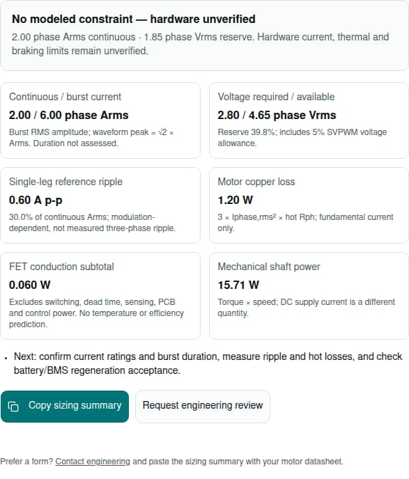
Live estimate: 2.00 phase Arms · 1.85 phase Vrms reserve
Illustrative values. Replace all fields with your motor data.
6–18 V model range; lowest measured voltage under load.
0–60,000 rpm, before the gearbox.
0–10 Nm at the motor shaft; account for gearbox losses.
0–30 Nm; at least continuous torque. Duration unmodeled.
Motor data & model assumptions
Example Kt=0.05, Ke=3, Rph=0.1 Ω, Lph=100 µH, 4 pole pairs, 50 kHz, hot Rds(on)=5 mΩ. Replace every value using your datasheet and operating conditions; Kt and Ke are independent inputs.
0.001–2; torque per phase RMS ampere, sinusoidal commutation.
0.01–150; verify RMS and line-line convention with supplier.
0.001–50 Ω; wye phase R = measured line-line R / 2.
1–10,000 µH; catalog low-frequency L may differ at PWM frequency.
Integer 1–50; pole pairs = number of magnetic poles / 2.
10–200 kHz model range; check actual drive and motor ratings.
0.1–100 mΩ per switch; assumption, not a GSD product rating.
Model range is an input limit, not a drive operating rating. Sinusoidal, non-salient PMSM with Id=0; trapezoidal constants need conversion. Read the method and limits.
- Continuous / burst current
- 2.00 / 6.00 phase Arms
- Burst RMS amplitude; waveform peak = √2 × Arms. Duration not assessed.
- Voltage required / available
- 2.80 / 4.65 phase Vrms
- Reserve 39.8%; includes 5% SVPWM voltage allowance.
- Single-leg reference ripple
- 0.60 A p-p
- 30.0% of continuous Arms; modulation-dependent, not measured three-phase ripple.
- Motor copper loss
- 1.20 W
- 3 × Iphase,rms² × hot Rph; fundamental current only.
- FET conduction subtotal
- 0.060 W
- Excludes switching, dead time, sensing, PCB and control power. No temperature or efficiency prediction.
- Mechanical shaft power
- 15.71 W
- Torque × speed; DC supply current is a different quantity.
- Next: confirm current ratings and burst duration, measure ripple and hot losses, and check battery/BMS regeneration acceptance.
Prefer a form? Contact engineering and paste the sizing summary with your motor datasheet.
1. Four decisions before selecting a 12V BLDC servo drive
Use loaded minimum voltage
At 12 V DC, the ideal linear SVPWM phase RMS ceiling is 4.90 V, not 12 V. Leave room for winding and controller losses.
Infineon IRMCx300 Reference ManualChoose PWM from the winding
Increasing PWM frequency lowers the reference ripple at fixed voltage and inductance. Verify actual phase ripple and total losses rather than assuming a fixed 80–100 kHz requirement.
Portescap: Understanding the Effect of PWM When Controlling a Brushless DC MotorBudget braking independently
A small bus capacitor may absorb only a tiny share of kinetic energy. Confirm the battery/BMS or an external energy sink can accept returned power.
Kollmorgen: AKD2G Low Voltage DC OperationRequest measured sensing evidence
Fast switching makes transient rejection and sampling behavior relevant. A nominal DC CMRR number alone does not establish current-loop quality.
Texas Instruments SBAA666: High Resolution, Small Form Factor Phase Current Sense for 48V Robotics and Servo Drives2. Reproducible method and parameter conventions
The checker assumes a balanced, non-salient sinusoidal PMSM, steady-state operation, Id=0, linear SVPWM, and known hot resistance and effective inductance. It does not model field weakening, saliency torque, current-loop transients or saturation. A BLDC catalog may use different conventions.
| Output | Equation / units | Boundary |
|---|---|---|
| Phase current | I = T / Kt; burst I = Tburst / Kt [Arms] | Motor-shaft torque; Kt must use phase RMS current. Burst duration is not evaluated. |
| Electrical speed | ωe = pole pairs × rpm × 2π/60 [rad/s] | Integer pole pairs, not pole count. |
| Back-EMF | ELL = Ke × rpm / 1000; Ephase = ELL / √3 [Vrms] | Ke is line-line RMS V/krpm. |
| Required voltage | Vreq = √[(Ephase + I Rph)² + (ωe Lph I)²] | Ld=Lq=Lph, Id=0. Enter Lph in µH; convert to H in the equation. |
| Available voltage | Vavail = 0.95 × Vdc / √6 [phase Vrms] | 5% reserve is an explicit screening assumption; actual modulation/voltage drop differs. |
| Reference ripple | ΔIpp = Vdc / (4 fPWM Lph) [A p-p] | Unipolar single-leg D=0.5 reference, not a bound on three-phase FOC ripple. |
| Motor / FET conduction | Pcu = 3 I² Rph; PFET,cond = 3 I² Rds,hot [W] | Fundamental current only; no complete drive efficiency or temperature estimate. |
The ideal power-balance check is Ke ≈ Kt × 104.72 / √3 with these conventions. A difference above 15% raises a convention warning; it does not automatically rewrite either input. The 20% voltage reserve and 30% reference-ripple flags are review heuristics, not certified operating limits.
Voltage basis: Infineon IRMCx300 Reference Manual. Ripple scheme distinctions: maxon Formulae Handbook. The remaining equations are stated circuit, power and three-phase transformations so that the calculation can be independently reproduced.
3. Compare 12V, 24V and 48V using the right current
| Quantity | 12 V DC | 24 V DC | 48 V DC |
|---|---|---|---|
| Average DC supply current Pinput/Vdc | 10 A DC | 5 A DC | 2.5 A DC |
| Harness loss at assumed 0.05 Ω | 5.00 W | 1.25 W | 0.3125 W |
| Harness loss relative to 48 V | 16× | 4× | 1× |
| Ideal linear SVPWM phase RMS ceiling | 4.90 V | 9.80 V | 19.60 V |
| Motor phase current at fixed torque and Kt | T/Kt | T/Kt | T/Kt |
The 16× comparison applies to this equal-power DC harness example. It is not a universal phase-current or inverter-loss multiplier. Higher bus voltage increases voltage capability for a given winding; it does not establish a universal rpm, PWM frequency or safety class. Select 12V when the source and winding support the required envelope; compare another voltage when current, speed or wiring costs dominate.
4. Low inductance: compare ripple before raising PWM
Use effective inductance at the operating current and switching conditions. Lower reference ripple does not by itself establish acoustic performance, rotor eddy loss, demagnetization temperature or continuous torque. Higher PWM also adds switching and control overhead. Portescap: Understanding the Effect of PWM When Controlling a Brushless DC Motor
| Assumed effective Lph | 20 kHz | 50 kHz | 100 kHz |
|---|---|---|---|
| 15 µH | 10.00 | 4.00 | 2.00 |
| 35 µH | 4.29 | 1.71 | 0.86 |
| 80 µH | 1.88 | 0.75 | 0.38 |
| 200 µH | 0.75 | 0.30 | 0.15 |
Peak-to-peak is the full excursion: 7.50 A p-p corresponds to ±3.75 A about the mean. Measure three-phase ripple with the intended modulation and motor. If losses or sampling prevent higher PWM, compare an appropriate winding or a validated output-inductor solution, including its size, resistance and control-loop effect.
5. GaN versus silicon: compare a complete power stage
GaN can enable fast switching and avoids silicon body-diode reverse recovery. These properties justify evaluation; they do not establish mandatory use, a guaranteed loss reduction or a universal gate-supply range. EPC: How GaN Inverters Are Redefining Humanoid Motor Control
| Decision dimension | What to compare | What remains unknown here |
|---|---|---|
| Conduction | Hot Rds(on) at actual gate voltage; package, PCB and shunt losses | Exact SKU, temperature and current rating |
| Commutation | Switching energy, output charge, reverse conduction and safe dead time | Measured switching loss across load and temperature |
| Gate drive | Recommended Vgs, absolute limits, driver UVLO and bootstrap behavior | Neither all silicon nor all GaN devices share one gate requirement |
| Sensing / EMC | PWM settling, transient immunity, emissions and layout | Measured current-loop accuracy and EMC results |
| Cost and packaging | BOM, layout effort, supply chain and cooling integration | Production quote and assembly/test cost |
Do not prescribe a universal 15 ns dead time: it must prevent shoot-through with the actual driver, FETs, propagation spread and temperature. This checker exposes hot Rds(on) and reports a conduction subtotal only. Total inverter watts, efficiency and junction rise require a characterized design.
Missing motor constants? Send your winding datasheet for review before relying on the estimates.
6. Battery sag and the real supply window
A nominal 12V label covers different source windows. A conventional 4.2 V/cell 3S lithium-ion charge ceiling is 12.6 V by arithmetic; the actual discharge floor, pulse capability and BMS behavior must come from the selected pack. Do not reuse that ceiling for LiFePO4 or automotive rails.
| Assumed total pack + harness R | Ohmic drop I×R | Loaded terminal voltage | Action |
|---|---|---|---|
| 22 mΩ | 0.330 V | 8.670 V | Verify measured hot/cold pulse impedance and drive UVLO. |
| 65 mΩ | 0.975 V | 8.025 V | Re-run the tool at loaded voltage, then check speed/torque margin. |
| 120 mΩ | 1.800 V | 7.200 V | Assess pack, wiring, connectors or torque profile. |
Use DC source current in this sag equation, not motor phase Arms. The checker does not infer pack resistance, battery current or BMS ratings. Confirm the highest charge/regeneration voltage too. Do not bypass cell or driver undervoltage protection with an arbitrary debounce time; coordinate fault handling with pack and drive specifications.
7. Regenerative braking: calculate energy and power separately
Worked conservative energy budget: total reflected inertia J=0.001 kg·m², motor speed 4,000 rpm, stop time 0.080 s. Assume all kinetic energy returns to the bus; friction, winding loss and the actual motion profile change the returned share. Gravity-driven loads can add energy. A battery or supply must explicitly support reverse power. Kollmorgen: AKD2G Low Voltage DC Operation
| Quantity | Calculation | Result / implication |
|---|---|---|
| Motor speed | ω = 4000 × 2π / 60 | 418.88 rad/s |
| Kinetic energy | E = ½ × 0.001 × ω² | 87.73 J |
| Capacitor headroom, 330 µF, 12→15 V | ΔE = ½ × 330×10⁻⁶ × (15²−12²) | 0.013365 J; 0.0152% of kinetic energy |
| Average returned power over 80 ms | E / 0.080 | 1096.6 W; instantaneous peak may be higher |
| Illustrative 3.3 Ω resistor at 14.5 V | P = 14.5² / 3.3 | 63.7 W at full conduction: cannot meet even this average budget |
A clamp threshold must clear the maximum normal source voltage and remain below actual protected ratings with tolerances. Choose the energy sink using peak power, pulse energy, repetition rate, thermal capacity, current limits and BMS-disconnect behavior. A TVS sized for wiring transients is not automatically an adequate repeated-stop energy sink. Request a validated braking design; the tool does not select a resistor or certify stopping behavior.
8. Field weakening is a separate operating envelope
Negative d-axis current can weaken the effective field to extend speed. It also consumes current capacity and changes torque capability. Microchip AN1078: Sensorless Field Oriented Control of a PMSM. The checker uses Id=0 and cannot predict this extended envelope.
As a vector arithmetic example only, equal-convention components Id=−7 A and Iq=10 A give a magnitude of √149=12.21 A; squared-current copper loss is 49% higher than for Id=0, Iq=10 A at the same resistance. This does not establish a universal speed gain or safe demagnetization limit. Obtain motor-specific magnet, thermal, current and maximum-speed limits.
9. Current sensing, feedback and mechanical integration
| Subsystem | Tradeoff | Required evidence |
|---|---|---|
| Low-side vs in-line sensing | Low-side sensing has PWM sampling-window constraints; in-line sensing must handle common-mode switching | Settling, transient rejection, filtering and sampling latency on the actual board |
| Encoder / resolver / Hall | Position accuracy, zero-speed operation, wiring and commutation alignment | Supported electrical interface, resolution, update rate and startup procedure |
| CANopen / CAN FD / EtherCAT | Transport, supported drive modes and host synchronization are separate choices | Exact firmware profile, timing budget, integration files and mode support |
| Flat / annular PCB / enclosed | Bore clearance, connector access, assembly and heat path affect integration cost | Dimensioned CAD, keepouts, insulation, mounting and cable bend requirements |
Current-sensing context: Texas Instruments SBAA666: High Resolution, Small Form Factor Phase Current Sense for 48V Robotics and Servo Drives. Profile context: CAN in Automation: CiA 402 series, drives and motion control. A feedback protocol such as BiSS-C is not a host fieldbus. Network cycle and synchronization figures depend on the implementation; no generic jitter or axis-count guarantee is made here.
10. Three reproducible screening cases
These are calculated examples, not customer case studies or measured motor performance. Load the matching preset in the tool to reproduce the results. All use Kt=0.05 Nm/phase Arms, Ke=3 line-line Vrms/krpm, hot Rph=0.1 Ω, 4 pole pairs and 0.1/0.3 Nm continuous/burst torque.
Balanced reference
12 V loaded, 1500 rpm, 100 µH, 50 kHz.
- Continuous / burst current
- 2.00 / 6.00 phase Arms
- Required / available voltage
- 2.80 / 4.65 phase Vrms
- Reference ripple
- 0.60 A p-p
Voltage and reference-ripple heuristics are clear; continuous current, cooling and braking still need qualification.
Try this preset in the toolBattery sag / speed limit
9 V loaded, 3000 rpm, 100 µH, 50 kHz.
- Continuous / burst current
- 2.00 / 6.00 phase Arms
- Required / available voltage
- 5.40 / 3.49 phase Vrms
- Reference ripple
- 0.45 A p-p
Voltage budget is exceeded. Reduce the speed target or compare another winding/bus; a faster PWM alone does not fix this.
Try this preset in the toolLow-inductance winding
12 V loaded, 1500 rpm, 20 µH, 20 kHz.
- Continuous / burst current
- 2.00 / 6.00 phase Arms
- Required / available voltage
- 2.80 / 4.65 phase Vrms
- Reference ripple
- 7.50 A p-p
Reference ripple is 7.50 A p-p. Compare effective L, PWM and filtering, then measure current and temperature.
Try this preset in the tool11. Validation, risks and the next engineering action
| Risk | Known here / remaining unknown | Minimum practical action |
|---|---|---|
| Motor convention mismatch | Equations documented; actual winding constants and saliency unknown | Confirm conventions with the motor supplier; convert or use a suitable model. |
| Overcurrent and overheating | Fundamental current and conduction subtotal only; SOA, burst duration and thermal path unknown | Compare SKU current ratings and duty cycle; measure worst-case hot hardware with intended mounting. |
| Braking / BMS opening | Conservative energy example; actual returned power and protection ratings unknown | Validate full-battery and disconnected-sink cases, pulse rating and stop repetition. |
| Cost or scenario mismatch | Higher PWM and packaging choices add design effort; production cost unknown | Compare total drive, filtering, cooling, validation and harness costs at intended quantity. |
| Safety or certification misuse | No certification or patient-use evidence supplied | Obtain applicable system requirements and actual certification/test evidence. |
For a supplier review, send motor part number and winding data, minimum/maximum loaded bus, motor speed, continuous and burst torque with duration, duty cycle, ambient/mounting, feedback and fieldbus, reflected inertia and stopping profile. If constants are unavailable, send the datasheet first rather than guessing inputs.
12. Sources, scope and review date
Sources checked October 27, 2026. These are manufacturer manuals, application notes and industry profile documentation. They support the stated methods and tradeoffs; none verifies GSD product performance or the calculated examples. Recheck source revisions and selected-device data before procurement. GaN Servo Drives owns the next review by April 27, 2027, or sooner if a cited source, model or supported product changes.
Infineon IRMCx300 Reference Manual
Section 4.3.5.1, PDF page 116: linear SVPWM line-line RMS limit Vdc/√2. Phase-neutral RMS limit Vdc/√6 follows from balanced three-phase conversion. The extra 5% reserve is our screening assumption.
maxon Formulae Handbook
Section 8.3, PDF page 46 (printed page 45), distinguishes PWM schemes and their ripple coefficients. The V/(4fL) single-leg reference does not establish actual three-phase FOC ripple or motor heating.
Portescap: Understanding the Effect of PWM When Controlling a Brushless DC Motor
PWM ripple, frequency and added-inductance tradeoffs. Effective inductance depends on excitation frequency. This is general motor guidance, not a GSD product qualification or a universal temperature prediction.
Texas Instruments SBAA666: High Resolution, Small Form Factor Phase Current Sense for 48V Robotics and Servo Drives
February 2025, sections 2 and 4: in-line sensing, PWM rejection and common-mode transients. Its 48V test circuit does not prove efficiency, thermal performance or operating range at 12V.
EPC: How GaN Inverters Are Redefining Humanoid Motor Control
April 6, 2026 supplier presentation: GaN switching, reverse recovery and motor-drive integration. It motivates evaluating GaN; it does not prove that GaN is mandatory or quantify savings for a particular 12V design.
Kollmorgen: AKD2G Low Voltage DC Operation
October 9, 2020, main supply output capacitance: regenerated energy raises DC bus voltage and may require an energy sink. Its AKD2G capacitance recommendations are not 12V component ratings.
Microchip AN1078: Sensorless Field Oriented Control of a PMSM
Field weakening section: negative d-axis current and the voltage/speed tradeoff. Maximum speed, permitted current and demagnetization limits remain specific to the motor and controller.
CAN in Automation: CiA 402 series, drives and motion control
Distinguishes drive profiles, supported modes and CANopen FD PDO mapping. A CAN FD physical/data link alone does not guarantee CiA 402 support, synchronization or interchangeable drives.
Public evidence is insufficient here for SKU-specific efficiency, temperature rise, rotor eddy-current loss, medical suitability, stock, lead time or braking capability. Confirm those items in a dated supplier response and test plan.
13. Frequently asked selection questions
Inputs and calculations
Can a 12V BLDC motor use a servo drive?
Yes, if the drive supports the actual loaded voltage range, winding, phase current, feedback and control mode. The 12V label alone does not establish compatibility. A servo also needs appropriate closed-loop feedback and tuning.
Which bus voltage should I enter?
Use the minimum voltage measured at the drive terminals under the intended load, including battery, BMS, fuse and harness drop. Check the highest charging and regenerative voltage separately against component and drive limits.
Can I paste catalog Kt and Ke directly?
Only after checking conventions. This checker uses Kt in Nm per phase RMS ampere and Ke in line-line RMS volts per krpm. Peak, DC block-commutated and dq constants may require conversion. Kt and Ke are not automatically linked.
Is phase current the same as supply current?
No. Phase RMS current follows torque and Kt. Average DC supply current follows total electrical input power divided by bus voltage. Phase current can be substantial at zero speed even when mechanical output power is zero.
What does a negative voltage reserve mean?
Under the stated sinusoidal Id=0 model, the required phase RMS voltage exceeds the reserved SVPWM budget. Reduce speed or torque, change the winding, or assess another bus voltage. It is not a prediction of an exact shutdown threshold.
Does the ripple result predict rotor temperature?
No. It is a unipolar single-leg D=0.5 reference using effective phase inductance. Actual three-phase ripple depends on modulation, motor state and inductance. Rotor temperature and losses need manufacturer data and measurements.
Selection and validation
Is GaN required for every 12V servo drive?
No. Compare actual hot resistance, switching energy, driver requirements, sensing performance and total system cost. Silicon can be appropriate. GaN is a candidate when switching frequency, size or losses justify it.
Can field weakening rescue a voltage-constrained case?
It may extend the speed range of a suitable motor/controller by applying negative d-axis current. This checker uses Id=0 and does not model it. Verify current, mechanical speed, magnet and overvoltage limits before commissioning.
Can a bench supply absorb braking energy?
Do not assume so. Check its specified reverse-power capability. A battery may also refuse charge when full or when its BMS opens. Calculate the returned energy and validate the energy sink and fault behavior.
Does 12V imply medical or touch-safety certification?
No. Nominal voltage does not establish product certification, insulation, fault protection, patient suitability or permitted surface temperature. Confirm the complete system requirements and supplier evidence for the intended application.
Does CAN FD guarantee CiA 402 or synchronous torque mode?
No. Transport capability and a drive profile are separate. Obtain the supported operating modes, object dictionary, timing behavior and integration files for the exact drive firmware.
What should I send for a drive recommendation?
Send the copied summary, motor part number and winding datasheet, loaded minimum/maximum bus, current conventions, burst duration, duty cycle, ambient and mounting, feedback/protocol, inertia and stopping profile. Confirm availability and ratings for the proposed SKU.
Continue with the motor data in hand
Use the tool to make assumptions visible, then request a drive recommendation with voltage, current, cooling and braking limits confirmed.