
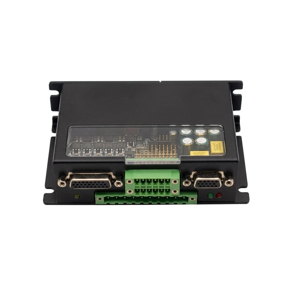
Regenerative Braking in Micro GaN Servo Drives: Sizing Brake Choppers, MLCC Bus Capacitance, and Shunt Resistors
Engineering and procurement guide for regenerative braking in low-voltage GaN servo drives: MLCC bus capacitor limits, brake chopper sizing, BMS disconnect risks, and RFQ checks.
As robotics OEMs transition from legacy silicon MOSFETs to Gallium Nitride (GaN) power stages in low-voltage motion control, power density has reached unprecedented levels. Operating at switching frequencies from 100 kHz to 200 kHz, GaN servo drives eliminate motor current ripple, slash thermal dissipation, and reduce the physical footprint of inverter boards to fit directly inside robot joints, automated guided vehicle (AGV) wheels, and autonomous mobile robot (AMR) chassis.
However, shrinking an inverter stage by 70% introduces an acute electrical vulnerability: the collapse of DC-link energy absorption capacity during regenerative braking.
When a high-inertia load decelerates rapidly or an emergency stop (E-stop) triggers, the servo motor transitions from a mechanical power sink into an electrical generator. In traditional silicon drives, massive aluminum electrolytic capacitor banks naturally absorbed this surge. In ultra-compact GaN servo drives, electrolytic capacitors are replaced by miniature Multi-Layer Ceramic Capacitors (MLCCs). While MLCCs deliver exceptional high-frequency ripple filtering and low equivalent series resistance (ESR), their total bulk capacitance is 20 to 50 times lower.
Compounding the challenge, GaN High Electron Mobility Transistors (HEMTs) possess zero avalanche breakdown capability (E_AS = 0). Unlike silicon MOSFETs, which can harmlessly absorb momentary voltage clamp energy across their parasitic body diode junction, a GaN HEMT subjected to a DC bus voltage overshoot exceeding its absolute maximum drain-to-source rating (V_DS,max) suffers catastrophic, permanent dielectric punch-through within nanoseconds.
This comprehensive guide delivers a first-principles engineering and procurement framework for managing regenerative energy in low-voltage (24V–60V) GaN servo drives. We analyze the physics of kinetic-to-electrical energy transfer, quantify the impact of MLCC DC-bias derating, examine the fatal "BMS disconnect" scenario in battery-powered robotics, compare four dissipation architectures, provide mathematical sizing equations for brake choppers and shunt resistors, and detail an RFQ sourcing checklist for OEM engineering teams.
TL;DR (Executive Summary):
- The Capacitance Vacuum: GaN's 100 kHz+ switching enables designers to replace bulky 2,000 µF electrolytic capacitors with 50–100 µF MLCC ceramic arrays. However, during rapid deceleration, the rate of DC bus voltage rise (
dV_bus/dt) increases by up to 40x. - Zero Avalanche Forgiveness: GaN HEMTs have no avalanche breakdown rating (
E_AS = 0). If bus overvoltage exceeds device limits (typically 80V or 100V for a 48V bus), the drive is destroyed immediately. - The Battery BMS Disconnect Trap: Lithium battery BMS protection circuits frequently trip on overcurrent or cell overvoltage during heavy braking, instantly disconnecting the battery sink and dumping all kinetic energy onto the tiny MLCC DC bus.
- Dissipation Hierarchy: Software dynamic braking (
I_dcurrent burning in motor windings) works for low-duty positioning cycles, but high-inertia axes and vertical loads mandate a hardware brake chopper circuit with internal or external shunt resistors. - Procurement Rule: Never specify a micro GaN drive based solely on continuous current; mandate verification of the brake chopper circuit's peak current rating, comparator response time (
under 500 ns), and overvoltage clamping hysteresis.
Review scope and baseline assumptions (October 2026): This technical guide applies to low-voltage DC servo drives operating from 24V, 48V, or 60V nominal DC buses powering permanent magnet synchronous motors (PMSM) and brushless DC (BLDC) motors in robotics, cobots, AGVs, AMRs, and aerospace actuators. All calculations assume standard engineering tolerances and ambient operating conditions up to +60°C.
1. The Physics of Regeneration: Kinetic Energy Transfer to the DC Bus
To design or procure an adequate energy dissipation solution, electrical engineers and procurement teams must first trace the physical chain of regenerative energy.
A servo motor in motion stores mechanical kinetic energy in both its rotating rotor and the coupled mechanical payload. When the drive controller commands deceleration, negative torque (T_decel) is commanded. The motor operates in the second or fourth quadrant of the torque-speed plane, functioning as an alternator driven by load inertia.
1.1 The Mathematical Governing Equations
The total mechanical kinetic energy (E_kin) stored in a rotating system with total combined inertia J_tot (motor rotor inertia J_m plus reflected load inertia J_L / N^2) spinning at angular velocity ω (in radians per second) is:
E_kin = 1/2 * J_tot ω^2 = 1/2 * (J_m + J_LN^2) (2π n60)^2Where:
J_totis the total inertia referred to the motor shaft (kg * m^2).nis rotational speed in revolutions per minute (RPM).Nis the gear reduction ratio.
During a controlled linear deceleration over time interval Δ t_decel, the mechanical deceleration power (P_mech) generated is:
P_mech = E_kinΔ t_decel = T_decel * ω2Not all mechanical energy reaches the DC bus. Energy is partially dissipated as heat in motor winding copper (3 I_rms^2 R_phase), iron core hysteresis, eddy currents, and mechanical friction in the gearhead (1 - eta_mech). Therefore, the net electrical regenerative energy (E_regen) delivered back through the inverter bridge into the DC bus is:
E_regen = E_kin * η_mech * η_motor * η_inverterIn high-performance robotics utilizing high-efficiency frameless brushless motors (eta ≈ 90%) and planetary or harmonic drives (eta ≈ 80%--90%), approximately 70% to 82% of the mechanical kinetic energy converts directly into electrical surge energy.
2. Why Micro GaN Servo Drives Are Vulnerable: The MLCC Dilemma & Zero Avalanche Breakdown
The primary vulnerability of compact GaN servo drives during braking stems from two distinct factors: the radical reduction of DC-link capacitance and the semiconductor physics of GaN HEMTs.
2.1 The DC-Link Capacitance Vacuum and Voltage Slew Rate (dV/dt)
In an inverter power stage, the DC-link capacitor bank functions as a localized energy buffer. When regenerative current I_regen flows into the DC bus and cannot be absorbed by the upstream power supply or battery, the charge accumulates directly in the capacitor bank:
Δ E_cap = 1/2 * C_eff (V_peak^2 - V_bus,nom^2)Solving for the peak transient DC bus voltage (V_peak):
V_peak = sqrtV_bus,nom^2 + 2 E_regenC_effThe rate of voltage rise on the DC bus (dV_bus/dt) is governed directly by the instantaneous regenerative current and the effective capacitance:
dV_busdt = I_regen(t)C_effIn a traditional silicon MOSFET drive operating at 16 kHz–20 kHz PWM, the DC link requires large aluminum electrolytic capacitors (typically 1,500 µF to 4,700 µF) to handle the low-frequency ripple current. Because C_eff is large, an incoming surge of 5 Joules causes only a modest, manageable voltage elevation.
In a micro GaN servo drive operating at 100 kHz–200 kHz, low-frequency ripple is virtually eliminated. Hardware designers replace the bulky electrolytic cans with an array of compact 1206 or 1210 surface-mount ceramic capacitors (MLCCs), reducing board height from 25 mm down to under 3 mm. However, the total installed capacitance is typically reduced to only 100 µF to 220 µF nominal.
2.2 The Trap of MLCC DC-Bias Voltage Derating
Compounding this reduction is a physical characteristic often missed during initial component procurement: ferroelectric ceramic DC-bias capacitance loss.
Class II dielectric materials (such as X7R, X7S, and X6S) experience a steep decline in effective capacitance when subjected to a continuous DC voltage bias. An MLCC rated at 22 µF with a 100V rating can lose 50% to 70% of its real capacitance when operating at a 48V DC bus level.
Consequently, a GaN drive board that appears to have 200 µF of installed capacitance on its schematic bill of materials (BOM) may provide an effective capacitance (C_eff) of only 60 µF to 80 µF at normal operating voltages.
Under this reduced capacitance, the voltage slew rate (dV_bus/dt) accelerates dramatically:
(dV_busdt)_GaN ≈ 30 x (dV_busdt)_SiliconA 25A regenerative current pulse charges an 80 µF effective MLCC bank at an astonishing rate of:
dV_busdt = 25 A80 x 10^-6 F = 312,500 V/s = 0.3125 V/µsIn just 32 microseconds, the DC bus climbs by 10V. In 96 microseconds, a 48V bus spikes past 78V, directly into the danger zone of 80V-rated power switches.
2.3 The Physics of GaN Failure: Zero Avalanche Breakdown (E_AS = 0)
In power electronics engineering, standard silicon power MOSFETs incorporate an inherent p-n junction body diode. When a drain-source voltage transient exceeds V_DS,max, the silicon device enters avalanche breakdown. In this mode, impact ionization absorbs energy safely across the junction, provided the pulse energy remains below the rated Single Pulse Avalanche Energy (E_AS, typically tens to hundreds of millijoules).
Gallium Nitride HEMTs are fundamentally different planar devices.
A GaN transistor forms its conduction channel through a high-mobility Two-Dimensional Electron Gas (2DEG) at the AlGaN/GaN heterojunction. It has no p-n junction and no avalanche breakdown mechanism.
If the electric field across the drain-to-gate or drain-to-source region exceeds the critical dielectric breakdown strength of the epitaxial GaN material:
- Impact ionization does not self-limit; instead, an instantaneous micro-plasma arc punctures the gate dielectric or burns through the drift region.
- The failure mode is a permanent, dead short-circuit between Drain, Source, and Gate.
- The high-side or low-side GaN device shorts directly across the DC bus, causing immediate shoot-through and catastrophic destruction of the entire phase leg.
Therefore, a GaN servo drive must never, under any operating condition or fault mode, experience a DC bus voltage that exceeds the absolute maximum V_DS rating of its transistors.
Table 1: DC-Link Energy Storage & Transient Comparison: Silicon vs. GaN (48V Nominal System)
| Engineering Metric | Traditional Silicon MOSFET Servo Drive | Ultra-Compact GaN Micro Servo Drive | Critical Procurement / Engineering Impact |
|---|---|---|---|
| Typical Switching Frequency | 16 kHz – 25 kHz | 100 kHz – 200 kHz | GaN enables smaller passives and eliminates audible motor noise. |
| DC-Link Capacitor Technology | Aluminum Electrolytic + Film bypass | Multi-Layer Ceramic Capacitors (MLCC, X7R/X6S) | Eliminates height bottlenecks; allows direct joint/wheel integration. |
| Nominal Installed Capacitance | 1,500 µF - 4,700 µF | 150 µF - 250 µF | Drastic reduction in energy storage buffer. |
DC-Bias Derated Capacitance (C_eff) | ≈ 1,500 µF (negligible derating) | 60 µF - 90 µF (50%–70% capacity loss) | True usable capacitance is far lower than schematic rating. |
Energy Buffer before 65V Trip (Δ E) | 1.44 J - 4.52 J | 0.058 J - 0.086 J | GaN has 25x–50x less energy absorption buffer! |
Voltage Rise Rate at 25A Regen (dV/dt) | 0.016 V/µs | 0.312 V/µs - 0.416 V/µs | Overvoltage threshold reached in microseconds. |
Semiconductor Avalanche Rating (E_AS) | 50 mJ - 500 mJ (Avalanche tolerant) | 0 mJ (Zero avalanche tolerance) | Transient spikes fatal to GaN; zero margin for delayed clamping. |
| DC Bus Voltage Margin Requirement | 15% - 20% safety margin sufficient | 35% - 45% margin mandatory | 48V nominal systems require 80V–100V GaN devices plus fast choppers. |
3. System-Level Hazards in 2026 Robotics: The Battery BMS Disconnect Trap
One of the most dangerous misconceptions in robotics design is assuming that a battery-powered platform (such as an AMR, AGV, or mobile manipulator) can inherently absorb regenerative braking energy.
While an electrochemical lithium-ion or lithium-iron-phosphate (LiFePO_4) battery pack has a massive capacity, the battery is isolated from the DC bus by an intelligent Battery Management System (BMS).
3.1 Why the BMS Disconnects During Deceleration
Modern industrial AMRs operating under safety directives (such as ISO 3691-4 and UL 3100) utilize protected lithium packs whose BMS monitors current, cell voltages, and temperatures at sub-millisecond sample rates. The BMS will deliberately open its charge protection solid-state switches (MOSFETs or contactors) under three common operational conditions:
- High State of Charge (SoC > 95%):
When an AMR operates near full charge, the individual cell voltages sit near their upper safety limit (e.g., 3.65V for LFP, 4.2V for NMC). A regenerative current spike causes instantaneous terminal voltage elevation (
V = V_OCV + I_chg * R_int). The BMS detects cell overvoltage and cuts off the charge path within microseconds to prevent lithium plating or thermal runaway. - Low Operating Temperature (under 5°C): In refrigerated cold-storage warehouses, lithium batteries cannot safely accept high charge currents due to slowed ion diffusion in the graphite anode. The BMS severely restricts or completely disables regenerative charge acceptance.
- Charge Overcurrent Protection (COP) Trip: During an emergency stop, the mechanical deceleration rate may push 40A to 80A of reverse current into the power rail. If this exceeds the maximum continuous charge current rating of the battery cells or BMS FETs, the BMS trips open instantaneously.
3.2 The Open-Circuit Bus Catastrophe
The instant the BMS disconnects the battery, the DC bus impedance transitions from milliohms to megaohms.
The kinetic energy of a 200 kg AMR moving at 1.5 m/s has nowhere to flow except into the micro GaN drive's derated 80 µF MLCC capacitor array. Without an autonomous, hardware-level brake chopper circuit, the DC bus voltage surges from 48V past 100V in less than 2 milliseconds, destroying the inverter stages on every drive connected to that common power rail.
4. Architectural Trade-offs for Regenerative Energy Dissipation
Robotics systems engineers and procurement teams must evaluate four primary methods for handling regenerative energy in GaN servo architectures. Each approach presents distinct mechanical, thermal, electrical, and bill-of-materials trade-offs.
4.1 Method 1: Software Dynamic Braking (Stator Flux Injection)
Advanced field-oriented control (FOC) firmware can mitigate DC bus pumping without external hardware by intentionally commanding a non-torque-producing reactive current component along the direct axis (I_d). By injecting negative I_d current into the motor windings during deceleration, electrical energy is converted directly into heat inside the motor stator resistance (P_diss = 32 (I_d^2 + I_q^2) R_phase).
- Pros: Zero BOM cost; requires no brake transistor or resistor; perfectly suited for space-constrained hollow-shaft robotic joints.
- Cons & Boundaries: Directly heats the motor stator. If duty cycles are tight, motor winding temperatures will exceed class F/H insulation limits (
>155^circC). Crucially, this method fails during an emergency stop if the drive trips into a fault state (Safe Torque Off - STO), because PWM switching ceases immediately, leaving the regenerative energy to freewheel uncontrolled through the GaN reverse conduction path onto the DC bus!
4.2 Method 2: Internal PCB Brake Chopper with Surface-Mount Pulse Resistors
The servo drive incorporates a dedicated power switch (a GaN FET or low-R_DS(on) silicon MOSFET) and high-pulse surface-mount thick-film or ceramic composition resistors directly on the drive PCBA.
- Pros: Self-contained, compact, and completely internal; no external wiring or chassis-mount assemblies required.
- Cons & Boundaries: Surface-mount resistors on an internal PCB have minimal thermal mass and rely on PCB copper conduction. They excel at absorbing single transient pulses (e.g.,
10 Jto30 Jover50 ms), but cannot sustain continuous duty cycles. Continuous dissipation is typically capped at 5W to 15W to prevent desoldering or overheating adjacent MCU logic.
4.3 Method 3: External Chassis-Mounted Shunt Resistor (Recommended for High Inertia)
The drive provides dedicated output terminals (BRK+ and BRK-) driven by its internal chopper switch, allowing the system integrator to wire an external wirewound or thick-film power resistor bolted directly to the robot's metallic chassis.
- Pros: Massive energy capacity. Chassis-mounted resistors in extruded aluminum housings can absorb
500 Jto5,000 Jpeak pulses and dissipate 50W to 500W continuous heat safely into the machine frame, keeping heat completely away from the sensitive drive electronics. - Cons & Boundaries: Requires external cabling, connector pins, and mechanical space on the chassis. The external wiring loop introduces parasitic inductance, which must be carefully damped.
4.4 Method 4: Active Supercapacitor / Bidirectional DC-DC Energy Buffer
In heavy-payload autonomous mobile robots and automated storage and retrieval systems (ASRS), kinetic energy is recaptured by a bidirectional buck-boost converter connected to a supercapacitor module.
- Pros: 100% green energy recovery; extends battery runtime by 8% to 15% in high-cycle stop-and-go warehouse operations; zero thermal heat generation.
- Cons & Boundaries: High system complexity, large physical volume, and substantial BOM cost premium (typically
150 to350 per axis). Only viable for large commercial logistics robots.
Table 2: Regenerative Energy Dissipation Architecture Comparison Matrix
| Evaluation Dimension | 1. Software Stator Flux Burn (I_d) | 2. Internal SMD Pulse Shunt | 3. External Chassis Resistor | 4. Supercap Active Recapture |
|---|---|---|---|---|
| Peak Pulse Energy Capacity | Moderate (20 J - 100 J, motor thermal limit) | Low (5 J - 35 J) | Very High (500 J - 10,000 J) | Extreme (>50,000 J) |
| Continuous Power Rating | Low (Limited by winding insulation) | Ultra-Low (5 W - 15 W) | High (50 W - 500 W) | High (Regenerated into battery) |
| BOM Cost Impact | `0.00 (Pure firmware) | Low (3 - 8 added to PCBA) | Moderate (15 - 45 resistor + cable) | High (`150 - $400 converter + caps) |
| Physical Enclosure Volume | Zero footprint | Zero external footprint | Moderate (Bolted to machine frame) | Bulky (Requires dedicated module) |
| STO / Emergency Stop Safety | Fails on STO trip (PWM gates shut off) | Works autonomously if hardware-driven | Works autonomously if hardware-driven | Requires active DC-DC control |
| Thermal Dissipation Location | Motor stator windings & rotor magnets | Inside drive PCBA enclosure | Machine aluminum chassis | None (Recaptured as charge) |
| Suitability for Vertical / Gravity Axes | Unacceptable (High duty overheat) | Poor (Thermal saturation in seconds) | Mandatory / Best Practice | Excellent for heavy cranes / lifts |
| Typical Target Applications | SCARA joints, dental / surgical tools | Cobot wrists, small pan-tilt heads | AMR wheel drives, robot lifters, AGVs | Automated pallet shuttles, ASRS |
5. Engineering Sizing Calculations for Choppers and Shunt Resistors
When specifying or procuring a GaN servo drive with an active brake chopper, engineering teams must calculate three critical electrical parameters: Resistance Value (R_shunt), Peak Pulse Power (P_pulse), and Continuous Average Power (P_cont).
       +V_BUS (48V Nominal)
           |
           +-----------------------+
           |                       |
       +-------+               +-------+
       | MLCC  |               | R_sh  | (Shunt Resistor)
       | Array |               +-------+
       +-------+                   |
           |                  +----+----+
           |                  | Chopper | (Brake Switch)
           |                  |  FET    |
           |                  +----+----+
           |                       |
       ----+-----------------------+---- GND
5.1 Step 1: Calculating Minimum and Maximum Shunt Resistance
The shunt resistor value must be bounded between a minimum resistance (R_min, to protect the brake switch from overcurrent) and a maximum resistance (R_max, to ensure energy is bled faster than the motor generates it).
1. Minimum Resistance (R_min):
Governed by the maximum pulsed current rating of the drive's internal brake transistor (I_brake,max):
R__shunt ≥ R__min = frac_V_clamp,max_I_brake,maxFor example, if the drive's chopper threshold activates at V_clamp = 65 V, and the brake FET has a peak pulsed current rating of 30 A:
R__min = (65 V) / (30 A) = 2.17 ΩSelecting any resistance value below 2.17 Ω risks tripping the drive's overcurrent protection or damaging the brake FET.
2. Maximum Resistance (R_max):
To prevent the DC bus voltage from rising during peak deceleration, the power dissipated by the resistor at the clamping voltage must equal or exceed the peak electrical regenerative power delivered by the motor:
P__elec,max ≤ frac_V_clamp,min^2_R_shunt => R__shunt ≤ R__max = frac_V_clamp,min^2_P_elec,maxIf peak regenerative power during an emergency stop is calculated at 850 W, and minimum clamping voltage is 62 V:
R__max = ((62 V)^2) / (850 W) = (3,844) / (850) = 4.52 ΩTherefore, the designer must select a standard resistor value strictly within the range:
2.17 Ω ≤ R__shunt ≤ 4.52 Ω -> Select 3.3 Ω or 3.9 Ω5.2 Step 2: Peak Power and Pulse Energy Calculations
Power resistors do not fail instantaneously from average thermal dissipation; they fail when a short, high-energy pulse melts the resistive element before heat can conduct to the exterior casing.
The peak instantaneous power (P_peak) absorbed by the chosen 3.3 Ω resistor at 65 V clamping is:
P__peak = frac_V_clamp^2_R_shunt = ((65 V)^2) / (3.3 Ω) = 1,280 WThe total energy dumped during a deceleration event of duration t_decel with average deceleration power P_avg,pulse ≈ 1/2 * P_peak is:
E__pulse = ∫_0^_t_decel P(t) dt ≈ (1) / (2) P__peak · t__decelFor an emergency stop lasting t_decel = 120 ms:
E__pulse = (1) / (2) (1,280 W) × 0.120 s = 76.8 JoulesProcurement Rule: The selected resistor datasheet must explicitly document a Single Pulse Energy Rating (E_pulse) of at least 100 Joules for a 120 ms pulse duration. Wirewound ceramic-core resistors excel at high pulse energy, whereas thin-film resistors will vaporize under this condition.
5.3 Step 3: Sizing for Continuous Average Power (P_cont)
In repetitive motion profiles (e.g., an AMR shuttling back and forth, or a packaging axis cycling 30 times per minute), the resistor accumulates continuous thermal energy.
The average power (P_avg) is determined by the cycle repetition time (t_cycle):
P__avg = frac_E_pulse_t_cycle = E__pulse · f__cycleIf the robot decelerates once every 4 seconds (f_cycle = 0.25 Hz):
P__avg = (76.8 J) / (4 s) = 19.2 WattsApplying a standard industrial engineering derating factor of 50% to account for elevated ambient temperatures inside enclosed robot chassis (+50°C):
P__rated ≥ frac_P_avg_0.50 = (19.2 W) / (0.50) = 38.4 WattsFinal Sourcing Specification: Sizing requires a 3.3 Ω ± 5%, 50-Watt continuous chassis-mount wirewound resistor with a minimum 120-Joule short-pulse capacity.
Table 3: Quantitative Shunt Resistor Sizing Matrix Across Robotic Payloads & Deceleration Profiles
| Robotic Application | Total Axis Inertia (J_tot) | Max RPM (n) | Decel Time (t_decel) | Peak Regen Power (P_peak) | Pulse Energy (E_pulse) | Optimal R_shunt Value | Resistor Power Rating (P_cont) | Recommended Hardware Placement |
|---|---|---|---|---|---|---|---|---|
| Cobot Wrist Joint (Axis 5/6) | 0.002 kg * m^2 | 3,000 | 40 ms | 110 W | 2.2 J | 15 Ω - 22 Ω | 10W Pulse SMD | Internal Drive PCB |
| Cobot Shoulder Joint (Axis 2) | 0.085 kg * m^2 | 2,500 | 150 ms | 950 W | 71.2 J | 3.9 Ω - 4.7 Ω | 50W Aluminum Housed | Bolted to Arm Casting |
| Light Logistics AMR (100 kg) | 0.150 kg * m^2 | 1,800 | 200 ms | 680 W | 68.0 J | 4.7 Ω - 6.8 Ω | 40W Wirewound | Bolted to Vehicle Chassis |
| Heavy Payload AMR (500 kg) | 0.650 kg * m^2 | 2,000 | 250 ms | 2,850 W | 356 J | 1.5 Ω - 2.2 Ω | 150W Chassis Mount | Vehicle Steel Frame |
| Automated Pallet Lifter (Z-Axis) | 0.400 kg * m^2 | 2,400 | 180 ms | 2,100 W | 189 J | 2.0 Ω - 2.7 Ω | 100W with Thermal Fuse | Extruded Frame Heat Sink |
| High-Speed Sorter / Diverter | 0.015 kg * m^2 | 4,500 | 30 ms | 830 W | 12.5 J | 4.7 Ω - 5.6 Ω | 75W High-Repetition | External Resistor Bank |
6. Sourcing Strategy & Procurement Checklist
Procuring high-frequency GaN servo drives requires an evaluation model that goes far beyond continuous current and torque-speed curves. Procurement teams, working alongside lead electrical systems engineers, must vet potential GaN drive vendors on chopper circuit transparency, hardware comparator latency, and thermal isolation.
The GaN Regenerative Braking Sourcing Checklist
- 1. Chopper Comparator Latency (under 500 ns): Does the drive utilize an autonomous, hardware-based comparator to trigger the brake switch? If the brake threshold is evaluated via firmware inside a microcontroller interrupt loop (which takes
10 µsto50 µs), the bus will spike past GaN breakdown limits before the software responds. Demand a hardware comparator response time under500 ns. - 2. Precise Voltage Clamping Hysteresis: Ensure the drive specifications define distinct activation and deactivation voltages. For a 48V nominal bus, standard best practice is activation at 63V–65V and deactivation at 58V–60V. Without adequate hysteresis, the chopper FET will oscillate into high-frequency linear ringing, causing rapid thermal breakdown.
- 3. MLCC DC-Bias Characterization Data: Request the vendor's actual effective capacitance (
C_eff) curve under nominal bus bias (e.g., at 48V and 60V). If the supplier only provides the nominal catalog rating (e.g., "240 µF") without DC-bias derating data, their engineering characterization is incomplete. - 4. Dedicated External Shunt Terminals: Inquire whether the drive hardware includes screw terminals, spring clamps, or connector pins (
BRK+,BRK-) for wiring an external power resistor. If the drive only offers internal SMD shunts, verify that its peak energy rating (E_pulse) matches your mechanical inertia calculations. - 5. Chopper Switch Transistor Specification: Ask which semiconductor device executes the brake chopping. If the vendor uses a high-
R_DS(on)silicon FET to save cost, the chopper switch itself will generate severe heat and risk thermal runaway during continuous cyclic deceleration. A matched GaN FET or an ultra-low-R_DS(on)(under 2 mΩ) silicon FET is required. - 6. Brake Resistor Thermal Overload Protection: Field wiring to an external brake resistor can short-circuit or suffer mechanical detachment. Does the drive feature desaturation detection, short-circuit protection on the chopper output, and a software
I^2tthermal accumulator model to shut down before burning out the resistor? - 7. Reverse Voltage / Power Supply ORing Integration: If the drive is powered from an AC-DC industrial power supply (which cannot sink reverse current), does the drive integrate an ideal diode / active ORing controller, or must an external reverse diode and clamp block be budgeted in the machine control cabinet?
- 8. Thermal Isolation Between Resistor and Logic: On micro servo drives featuring internal brake resistors, inspect the PCB layout to verify that the power resistor is physically isolated from the microcontroller, gate drivers, and magnetic encoder IC. High-temperature thermal cycling on the resistor will degrade encoder accuracy and drift ADC reference voltages.
7. Frequently Asked Questions (FAQ)
Q1: Why can't we simply set our GaN servo drive's deceleration time longer to prevent overvoltage?
A: Extending the deceleration ramp time (t_decel) decreases the peak deceleration power (P_decel = E_kin / t_decel), which allows ambient losses and power supply bleeders to absorb more energy. However, in industrial robotics, deceleration time is dictated by cycle-time targets (takt time) and safety standards. Furthermore, during an Emergency Stop (E-Stop) or Category 0/1 stop event, the motor must arrest motion within milliseconds to prevent collisions or personal injury. Relying on slow decel ramps leaves the machine unprotected against real-world emergency trip events.
Q2: What happens if an external brake resistor's wiring has high parasitic inductance?
A: Because the brake chopper switches high currents (20A to 50A) with sub-microsecond transition edges, any stray inductance in the wiring to an external resistor produces high-voltage ringing spikes (V = L_trace * di/dt). If the wiring runs 2 meters with unshielded loose wires (L ≈ 2 µH), switching a 30A chopper in 100 ns generates an inductive spike of:
V__spike = 2 × 10^_-6 × (30) / (100 × 10^_-9) = 600 V
```text
This spike will immediately destroy the brake chopper FET. **Engineering Solution:** Keep brake resistor wiring as short as possible (`under 30 cm`), use tightly twisted-pair cables, and ensure the drive has a localized high-voltage ceramic snubber placed directly across the chopper switch terminals.

### Q3: Can GaN servo drives regenerate power back into an AC-DC power supply?
**A:** Standard commercial AC-DC power supplies (e.g., standard DIN-rail 48V power units) utilize a diode rectifier or forward converter output stage. **They cannot sink reverse current.** When regenerative current flows backward toward the power supply, the supply's output diodes block it, causing the power supply to enter an overvoltage trip shutdown. If operating from an AC-DC front end, you must either install an active shunt regulator module directly across the 48V bus or ensure every GaN servo drive on the bus has an enabled internal brake chopper.

### Q4: What is the difference between dynamic braking via low-side FET shorting and dynamic braking via a brake chopper?
**A:** In low-side FET shorting (often commanded by a motor driver `BRAKE` pin or during STO Category 1), all three low-side GaN FETs in the inverter bridge are turned on simultaneously, while all high-side FETs remain off. This shorts the three motor phase terminals together. The motor back-EMF creates a circulating current entirely within the motor windings and the low-side switches.

The kinetic energy is dumped **100% as heat into the motor windings**. While this prevents any voltage from pumping onto the DC bus, it provides zero deceleration torque at near-zero speeds, generates substantial thermal stress inside the motor, and cannot be modulated smoothly. A dynamic brake chopper, by contrast, maintains full FOC position and velocity trajectory control throughout the deceleration maneuver, transferring the heat outside the motor into a controlled resistor.

### Q5: How do we size a brake resistor for a vertical Z-axis experiencing gravity overhaul?
**A:** Vertical axes present a continuous regenerative load. When lowering a payload of mass `m` at constant downward velocity `v`, the potential energy lost per second represents continuous electrical power generation:
P__gravity = m · g · v · η__mech$$
Because this energy is continuous (not an intermittent pulse), the shunt resistor's continuous wattage rating must exceed P_gravity for the entire duration of the descent stroke. An internal SMD resistor will overheat and fail within seconds on a vertical axis; an external chassis-mounted power resistor with an integrated bimetallic thermal switch is strictly required.
Q6: If we use 100V GaN FETs on a 48V system, do we still need a brake chopper?
A: Yes. While a 100V GaN FET provides a generous 52V margin above the nominal 48V operating point under steady state, an unmitigated emergency stop on an AMR can easily pump a small 80 µF MLCC bus from 48V to over 120V in under 3 milliseconds. Furthermore, running a 48V bus near 85V–90V severely stresses the input filter capacitors, gate driver ICs, and DC-DC auxiliary power regulators (which are often rated for 75V or 80V maximum). Relying on transistor voltage headroom instead of active clamping is a recipe for field failures.
8. Conclusion: Protecting the Wide-Bandgap Advantage
The adoption of Gallium Nitride in low-voltage servo drives has unlocked transformative architectural opportunities: eliminating industrial control cabinets, integrating drives directly inside robotic limbs, and achieving dynamic bandwidths once deemed impossible.
However, high power density cannot bypass the laws of conservation of energy. When a moving robotic arm or a 500-kg AMR arrests motion, kinetic energy must convert into electrical energy, and that electrical energy must be dissipated safely.
In the miniaturized, MLCC-dominated world of GaN motion control, the traditional capacitive safety buffer has disappeared. Because GaN HEMTs provide zero avalanche tolerance, managing regenerative braking is no longer an optional afterthought—it is a foundational system-level design requirement.
By calculating kinetic energy transfer accurately, accounting for MLCC DC-bias derating, designing around battery BMS disconnect conditions, and sourcing drives with validated, sub-microsecond brake choppers and properly sized shunt resistors, OEM engineering teams can harness the full power and efficiency of GaN without sacrificing industrial reliability.
Accelerate Your Motion Control Architecture
Are you designing a next-generation AMR, collaborative robot, or high-inertia actuator module?
Explore our production-ready GaN Low-Voltage Servo Drives featuring integrated high-speed hardware brake choppers, or inspect our high-current AMR and Mobile Robot Servo Drives engineered for harsh battery-powered platforms.
If your axis requires custom mechanical mounting or extreme-pulse external shunt integration, talk directly with our engineering team for an OEM Custom Solution optimized for your exact thermal, electrical, and motion requirements.
Sources & References
- Texas Instruments Application Report: TIDA-010070: Protected DC Bus Input Power and Control Power Supply Reference Design for Low-Voltage Servo Drives. ti.com/tool/TIDA-010070
- Texas Instruments Technical White Paper: Gallium Nitride (GaN) Solutions in Motor Drive Applications & Anti-Voltage Surge (AVS) Algorithms. ti.com/product-category/motor-drivers/gallium-nitride/overview.html
- Efficient Power Conversion (EPC Corporation): GaN for Motor Drives: Inverter Design, Power Density, and DC-Link Capacitance Optimization. epc-co.com/epc/applications/gan-for-motor-drives
- Power Electronics News: Capacitor Selection and Decoupling Strategies in High-Frequency Wide-Bandgap Inverters. powerelectronicsnews.com/gan-motor-drives-shrink-inverter-size-and-increase-efficiency
- Control Engineering: Managing Regenerative Energy and DC Bus Dynamics in Modern Servo Systems. controleng.com/articles/when-to-use-decentralized-motor-control
Author

dV/dt)2.2 The Trap of MLCC DC-Bias Voltage Derating2.3 The Physics of GaN Failure: Zero Avalanche Breakdown (E_AS = 0)Table 1: DC-Link Energy Storage & Transient Comparison: Silicon vs. GaN (48V Nominal System)3. System-Level Hazards in 2026 Robotics: The Battery BMS Disconnect Trap3.1 Why the BMS Disconnects During Deceleration3.2 The Open-Circuit Bus Catastrophe4. Architectural Trade-offs for Regenerative Energy Dissipation4.1 Method 1: Software Dynamic Braking (Stator Flux Injection)4.2 Method 2: Internal PCB Brake Chopper with Surface-Mount Pulse Resistors4.3 Method 3: External Chassis-Mounted Shunt Resistor (Recommended for High Inertia)4.4 Method 4: Active Supercapacitor / Bidirectional DC-DC Energy BufferTable 2: Regenerative Energy Dissipation Architecture Comparison Matrix5. Engineering Sizing Calculations for Choppers and Shunt Resistors5.1 Step 1: Calculating Minimum and Maximum Shunt Resistance1. Minimum Resistance (R_min):2. Maximum Resistance (R_max):5.2 Step 2: Peak Power and Pulse Energy Calculations5.3 Step 3: Sizing for Continuous Average Power (P_cont)Table 3: Quantitative Shunt Resistor Sizing Matrix Across Robotic Payloads & Deceleration Profiles6. Sourcing Strategy & Procurement ChecklistThe GaN Regenerative Braking Sourcing Checklist7. Frequently Asked Questions (FAQ)Q1: Why can't we simply set our GaN servo drive's deceleration time longer to prevent overvoltage?Q2: What happens if an external brake resistor's wiring has high parasitic inductance?Q6: If we use 100V GaN FETs on a 48V system, do we still need a brake chopper?8. Conclusion: Protecting the Wide-Bandgap AdvantageAccelerate Your Motion Control ArchitectureSources & ReferencesMore Posts
How to Select a 48V EtherCAT Servo Drive for Humanoid Robot Joints
Evaluating SIL3 STO in Micro GaN Servo Drives: A Procurement and Compliance Guide
Evaluate SIL3 STO in micro GaN servo drives globally: compare isolation, CMTI, certification evidence, supplier risks, and RFQ checks. Request review.
GaN vs Silicon MOSFETs in Low-Voltage Servo Drives: Thermal & Power Density Compared