
12V Board-Level Servo Drive
Use this 12V board-level servo drive worksheet to size your motor and carrier. Check voltage and connector loading, then plan hardware validation. It covers an embedded three-phase servo power stage; serial hobby-servo adapter boards require a different selection process.
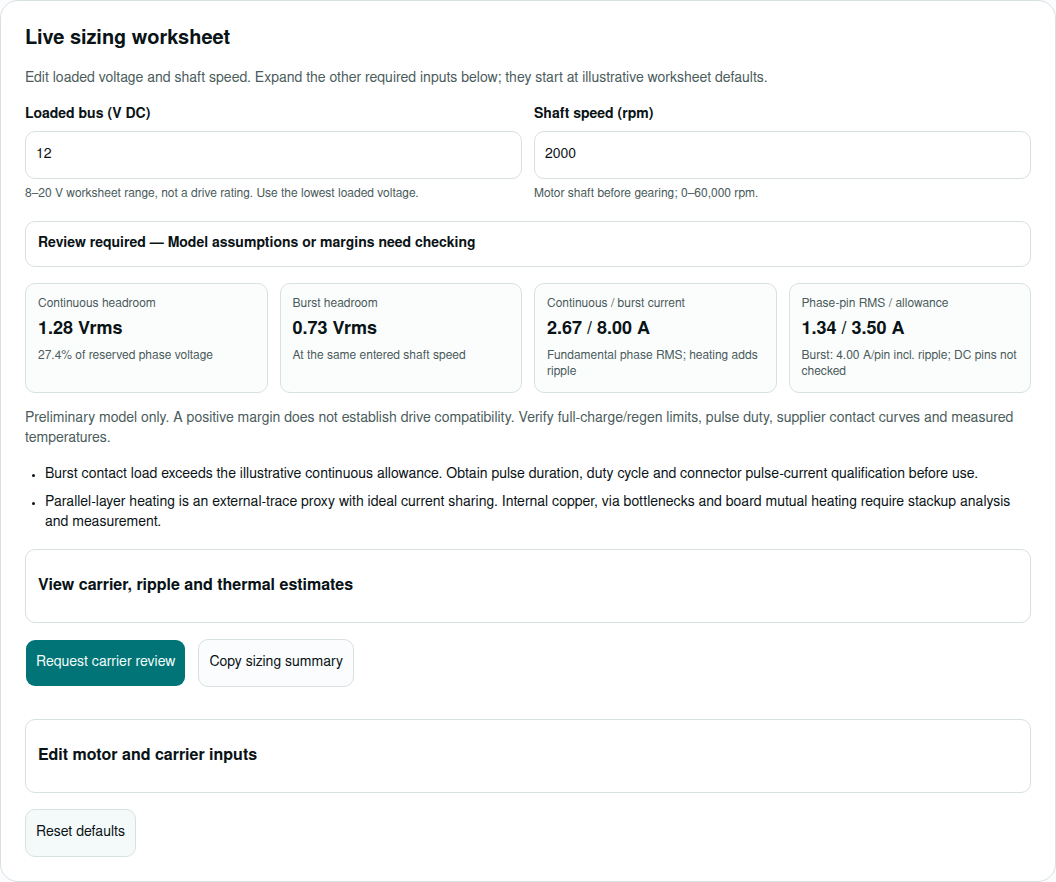
Live sizing worksheet
Edit loaded voltage and shaft speed. Expand the other required inputs below; they start at illustrative worksheet defaults.
8–20 V worksheet range, not a drive rating. Use the lowest loaded voltage.
Motor shaft before gearing; 0–60,000 rpm.
Continuous headroom
1.28 Vrms
27.4% of reserved phase voltage
Burst headroom
0.73 Vrms
At the same entered shaft speed
Continuous / burst current
2.67 / 8.00 A
Fundamental phase RMS; heating adds ripple
Phase-pin RMS / allowance
1.34 / 3.50 A
Burst: 4.00 A/pin incl. ripple; DC pins not checked
Preliminary model only. A positive margin does not establish drive compatibility. Verify full-charge/regen limits, pulse duty, supplier contact curves and measured temperatures.
- Burst contact load exceeds the illustrative continuous allowance. Obtain pulse duration, duty cycle and connector pulse-current qualification before use.
- Parallel-layer heating is an external-trace proxy with ideal current sharing. Internal copper, via bottlenecks and board mutual heating require stackup analysis and measurement.
View carrier, ripple and thermal estimates
- Required / available phase voltage
- 3.38 / 4.65 Vrms
- PWM ripple proxy
- 0.75 A p-p; 28.1% of continuous current
- Phase contact / trace drop
- 6.0 / 2.7 mV
- 3-phase contact / trace I²R loss
- 0.048 / 0.021 W
- Legacy external-trace ΔT proxy
- 0.06 °C; not IPC-2152 stackup validation
- Illustrative GaN / Si bridge loss
- 0.14 / 0.40 W; assumed parts, incomplete loss model
- Assembly thermal proxy
- 41.0 °C; 105°C worksheet threshold, not a device rating
Thermal proxy combines bridge, connector, trace and 0.5W auxiliary allowance through one assumed thermal resistance. It cannot predict a component junction temperature. Review equations and exclusions.
Edit motor and carrier inputs
Four decisions before choosing a board-level drive
The tool screens a balanced sinusoidal motor at Id = 0. It gives a direction for a design review, with a separate report layer below. No specific module rating or customer performance is established by this page.
| Decision | Evidence / calculation | Release condition |
|---|---|---|
| Check the lowest loaded bus | At 12V, the reserved linear phase ceiling is 4.65 Vrms; at 10.5V, 4.07 Vrms. TI SPRA524 — Space-Vector PWM | Repeat at worst-case loaded voltage and verify burst headroom. The 5% reserve is chosen here. |
| Size contacts for the populated connector | Current sharing and ambient conditions matter. Harwin — Derating Curves and Current Ratings | Obtain supplier curves and qualify pulse load; 0.70/0.85 are worksheet assumptions. |
| Treat copper heating as a proxy | The legacy fit uses k = 0.048, b = 0.44, c = 0.725. TI SNVA766 — PCB Layout Guideline for Automotive LED Drivers | Validate stackup, vias, neck-downs and enclosure temperature on hardware. |
| Compare complete loss and integration cost | GaN motor-drive examples are device-specific. EPC — GaN in Motor Drive Applications | Confirm measured loss, controller overhead, carrier NRE and qualification effort. |
1. Voltage budget: continuous and burst torque
For balanced sinusoidal phase RMS current, I = torque / Kt. Convert line-line RMS back-EMF to phase-neutral RMS before adding resistance and inductive voltage. The worksheet includes the motor winding, carrier trace and connector resistance in each phase.
SVPWM background: TI SPRA524 — Space-Vector PWM. Voltage values in this guide are phase-neutral RMS unless explicitly marked line-line. DC supply current cannot be inferred directly from phase current.
2. Reproducible scenarios, including an infeasible high-speed case
These are synthetic worksheet examples, not customer deployments or measured outcomes. Load the matching preset in the tool and inspect all motor and carrier inputs. The table is generated by the same engine, so results remain reproducible.
| Example / premise | Speed / bus | Phase continuous / burst | BEMF line-line | Continuous / burst headroom | Decision / next step |
|---|---|---|---|---|---|
| Exoskeleton Joint Actuator | 2200 rpm / 12 V | 2.92 / 8.75 Arms | 6.38 Vrms | 0.68 / 0.04 Vrms | Voltage is within the model ceiling. Review contact pulse load and carrier/thermal assumptions. |
| AGV Steering Micro-Actuator | 1800 rpm / 11.5 V | 4.89 / 12.22 Arms | 4.90 Vrms | 1.25 / 0.60 Vrms | Voltage is within the model ceiling. Review contact pulse load and carrier/thermal assumptions. |
| High-Speed Medical Handpiece | 35000 rpm / 12 V | 2.14 / 5.00 Arms | 14.70 Vrms | -4.32 / -4.97 Vrms | Voltage constraint: reduce speed or review winding/bus. Do not assume field weakening. |
| Autonomous Gimbal / Optical Pod | 600 rpm / 12 V | 0.94 / 2.12 Arms | 3.08 Vrms | 2.54 / 2.11 Vrms | Voltage is within the model ceiling. Review contact pulse load and carrier/thermal assumptions. |
For example, Ke = 0.42 V line-line RMS/krpm at 35,000 rpm produces 14.70 V line-line RMS back-EMF. It already exceeds the linear voltage available from a 12V bus before adding winding drop; a higher PWM frequency cannot recover this missing voltage.
3. Connector choice: resistance, pulse duty and service access
| Option | Benefit | Cost / risk | Evidence required |
|---|---|---|---|
| Mezzanine header | Replaceable module; compact carrier | Contact heating, mating access and vibration qualification | Exact pair, plating, populated-contact derating and pulse profile |
| Dedicated power connector | Separates motor/DC power from signals | Larger footprint, cable retention and assembly cost | Hot-condition rating, wire gauge and contact resistance |
| Castellated / direct solder | Low profile; no separable contact interface | Rework cost, solder fatigue and process yield | Module land pattern, joint inspection and mechanical support |
Connector guidance: Harwin — Derating Curves and Current Ratings. Neither parallel pin count nor a gold finish by itself establishes vibration life. Use a supplier qualification plan and measure resistance after stress testing.
4. Carrier copper and assembly: follow the actual current path
| Condition | What the worksheet does | What to validate |
|---|---|---|
| One uniform external trace | Legacy IPC-2221 fit; 35 µm per oz; copper resistivity 1.99e−8 Ωm at 60°C | Finished thickness, local hot spots and ambient temperature |
| Parallel conductor layers | Divides current equally and applies the external fit to each layer | Actual current sharing, internal-layer thermal environment and stitching vias |
| Via-in-pad assembly | No solder-joint prediction | Package assembly guide, filled/capped options, paste process and inspection; no zero-void guarantee |
| Multi-axis carrier | One-axis losses only | Shared DC feed, simultaneous loads, hot spots and return-current routing |
The legacy equation is documented in TI SNVA766 — PCB Layout Guideline for Automotive LED Drivers. The tool does not claim IPC-2152 conformity. There is no universal minimum layer count or copper weight for every 12V board-level drive.
5. GaN and thermal trade-offs: separate assumptions from ratings
GaN can support short dead-time and higher PWM frequency in suitable designs; the linked EPC — GaN in Motor Drive Applications describes a particular EPC evaluation setup. Device and layout choices determine the result. Do not transfer its timing or efficiency to an unspecified 12V module.
| Parameter | Worksheet value | Missing information / action |
|---|---|---|
| GaN / silicon on-resistance | 6 / 14 mΩ | Hot Rds(on), actual part numbers and gate voltage |
| GaN / silicon transition time | 3 / 16 ns; Si Qrr = 35 nC | Actual switching-energy curves, Coss and operating conditions |
| Conduction current | Iheat = √(Ifund² + ΔIpp²/12), used for bridge, contacts and copper | Real PWM waveform, harmonics and motor behavior |
| Auxiliary power | 0.5W allowance | Measure controller, gate driver, shunt and supply losses |
| Thermal resistance assumptions | 35 / 8.5 / 2.5 °C/W for convection / chassis / cold plate | Actual multi-component thermal paths and TIM isolation |
| Thermal / trace review thresholds | 100°C thermal warning; 105°C constraint / 30°C trace rise | Chosen worksheet thresholds; replace with component and assembly limits |
Loss-term reference: TI — Power Loss Equations for a 3-Phase Inverter. The simplified switching model assumes one hard turn-on/off pair per half-bridge per PWM cycle.
The comparison excludes dead-time loss, output-capacitance energy, detailed gate power and measured hot resistance. Total assembly proxy includes bridge, connector, carrier trace and the 0.5W allowance. Motor copper loss is excluded. Higher PWM reduces the ripple proxy while increasing switching activity; neither loss percentage nor efficiency is guaranteed.
6. DC link and regeneration: voltage limits come first
Capacitor energy headroom is ΔE = ½C(Vmax² − Vstart²). As an arithmetic example, 1,000 µF between 12V and an assumed 15V ceiling stores only 0.0405 J of additional energy. This is not a recommended clamp voltage: the selected module’s component limits and full-charge voltage decide the permissible ceiling.
Compare recoverable kinetic energy and stopping time with the supply’s sink capability, capacitor energy headroom and resistor pulse-energy curve. For an illustrative 1.5 Ω brake resistor at 15V, instantaneous dissipation is 150W; a 50W continuous label alone does not qualify that pulse.
Use the exact capacitor DC-bias and ripple-current curves. Murata — Ceramic Capacitor DC Bias FAQ explains the bias dependence, but does not establish a universal 42% capacitance reduction. Ripple-current stress depends on modulation, power factor and the bank; do not apply one phase-current multiplier to every inverter.
7. Multi-axis communication and return paths
TI SLLA270 — CAN Physical Layer Requirements describes CAN physical-layer concepts and split termination. It does not establish a protocol stack, CAN-FD speed or EtherCAT compatibility for a GSD module. EtherCAT requires a suitable slave controller and software implementation, not a PHY alone.
Follow the module’s ground and isolation reference layout. Keep switch-node and commutation loops away from sensing and encoder paths, preserve signal return continuity and check common-mode range. Do not create arbitrary ground splits under high-speed pairs.
8. Calculation method, limits and reproducibility
All computations run synchronously in your browser with no network wait. Invalid input hides the output; there is no intermediate calculation state. R below includes hot winding resistance plus one phase’s uniform carrier trace and equivalent contact resistance.
| Output | Equation / convention | Validity limit |
|---|---|---|
| Current and speed | I = T / Kt; ωe = pole pairs × rpm × 2π/60 | Sinusoidal phase RMS Kt; shaft torque, not gearbox output |
| Back-EMF | Ephase = Ke × rpm / (1000√3) | Ke in V line-line RMS/krpm; confirm catalog convention |
| Required phase voltage | Vreq = √[(Ephase + I R)² + (ωe L I)²] | Id = 0, equal d/q inductance, steady state; evaluated for continuous and burst |
| Available phase voltage | Vavail = 0.95 × Vdc / √6 | Linear SVPWM with a chosen 5% voltage reserve |
| Ripple proxy | ΔIpp = Vdc / (4 fsw L) | D = 0.5 buck-like reference; not a guaranteed three-phase waveform bound |
| External-trace heating proxy | ΔT = [ (Iheat / layers) / (0.048 × A_layer^0.725) ]^(1/0.44) | A_layer in square mils; legacy IPC-2221 external fit; no temperature clipping |
| Phase-path and bridge conduction loss | Pcontacts = 3 Iheat² Rcontact/N; Ptraces = 3 Iheat² Rtrace; Pcond = 3 Iheat² Rds | Iheat = √(Ifund² + ΔIpp²/12); ideal sharing and triangular ripple reference |
| Bridge switching / Si recovery proxy | Psw = 3 × ½ Vdc (2√2/π × Ifund) (tr+tf) fsw; Prr = 3 Qrr Vdc fsw | One hard turn-on/off pair per leg per cycle; fixed illustrative Qrr; ripple-dependent switching energy excluded |
| Thermal proxy | Tambient + (Pbridge + Pcontacts + Ptraces + 0.5W) × θ | One lumped path; missing device-specific loss and thermal data |
Motor constant mismatch above 15%, ripple above 35%, fewer than 20 PWM periods per electrical cycle, tight voltage reserve, pulse contact load and multiple parallel layers trigger review. Nonpositive continuous or burst voltage margin, continuous contact overload, trace proxy above 30°C rise, or assembly thermal proxy above 105°C trigger a modeled constraint. These thresholds are worksheet choices, not standards or hardware guarantees.
Burst phase-pin RMS above the entered reference pin rating also triggers a modeled constraint until pulse qualification is available. A parallel-layer caveat conservatively requests review because inner-layer heating is unknown; it does not mean that adding copper worsens the computed temperature. The model does not check drive continuous/peak ratings, burst duration, motor thermal limits, saturation, saliency, current-loop stability, DC-input pin heating, battery sag dynamics, regenerative protection or functional safety. Use it to prepare a review, then validate the selected hardware.
9. From worksheet to prototype decision
| Risk / decision | Consequence | Minimum action / alternative |
|---|---|---|
| Misuse: positive worksheet result treated as approval | Underrated drive, contacts or protection | Compare the complete torque-speed duty and bus range with a revision-controlled module datasheet |
| Cost: compact module needs a custom carrier | PCB NRE, assembly yield, rework and test fixtures | Compare total integration cost with a connectorized enclosed drive; obtain a carrier fabrication quote |
| Scenario mismatch: high Ke at high speed | Voltage saturation despite low current | Reduce speed, choose a suitable winding, or review a higher-voltage system with all component ratings |
| Thermal mismatch: isolated or low-conductivity chassis | Hot spots despite a low thermal proxy | Characterize TIM, isolation and heat paths under the worst enclosure conditions |
| Multi-axis braking or battery disconnect | Shared-bus overshoot | Measure energy and overshoot; qualify a sink/clamp and fault response before loaded tests |
Start bring-up with a current-limited supply and unloaded motor. Confirm pinout, winding resistance and encoder direction. Then increase load in controlled steps while recording bus voltage, phase current, contact temperature and component temperatures. Exercise burst/repetition and braking only with a qualified protection setup.
10. Engineering questions
Inputs and results
Is this a 12V board-level drive product selector?
It is a preliminary motor-and-carrier worksheet. It does not select or approve a specific GSD module. Ask for the exact module datasheet, pinout, voltage range and firmware options before purchase.
Should I enter nominal or loaded battery voltage?
Enter the lowest loaded bus voltage at the drive terminals for voltage headroom. Separately verify full-charge voltage, transients and regeneration against every component rating. Repeat the worksheet for other supply corners.
Is phase RMS current the same as battery current?
No. Phase current follows torque divided by the compatible torque constant. Battery current follows electrical input power divided by bus voltage, with losses and operating duty. A low-speed joint can have high phase current and modest battery power.
Can I enter gearbox output torque?
Convert it to motor-shaft torque first using gear ratio and efficiency. Use motor shaft speed. Otherwise the current and voltage estimates can be wrong by the gear ratio.
Why do torque and back-EMF constants disagree?
Confirm RMS versus peak, phase-neutral versus line-line and winding connection. Under the worksheet sinusoidal convention, Ke in V line-line RMS/krpm equals Kt in Nm/Arms times 1000 × 2π / (60√3). A difference above 15% triggers review.
Does a positive continuous margin also cover acceleration?
No. The worksheet checks burst torque at the same speed separately. A burst with negative voltage headroom cannot be delivered in this model. Positive burst headroom still requires pulse current and duty-cycle qualification.
Carrier integration
How many header pins should share a motor phase?
Use the supplier’s populated-contact derating curve and temperature limit. The tool assumes equal sharing and applies illustrative 0.70 multi-pin or 0.85 single-pin margins. These are editable-design assumptions to verify, not IEC requirements or connector ratings.
Can internal copper planes be treated like external traces?
Not for a release decision. The tool divides current evenly between layers and uses an external-trace temperature proxy. Internal layers, adjacent planes, vias and local neck-downs need stackup analysis and measurement.
Does IPC-4761 Type VII guarantee zero solder voiding?
No. Filled and capped via-in-pad can address solder wicking, but acceptable via construction, fill material, pad geometry, paste and reflow must follow the package assembly guidance and PCB supplier process. Inspect the actual solder joint.
Should encoder ground always be split from power ground?
Follow the selected module and transceiver layout guidance. Keep switching loops compact and preserve return paths under signals. A universal star-ground split can interrupt return currents and worsen noise; confirm layout with measurement.
Protection and alternatives
Can I use a fixed 15.2V brake clamp for every 12V drive?
No. Choose thresholds from full-charge voltage, component limits, tolerances and transient overshoot. Size the resistor and switch for peak power, braking energy, repetition and cooling. The worksheet does not validate regeneration or a safety stop.
How much MLCC capacitance is retained at 12V?
It depends on part number, case size, dielectric, temperature and aging. Check the manufacturer DC-bias data. A 25V voltage rating alone does not imply a particular effective capacitance at 12V.
Does a GaN stage always reduce losses by 65%?
No. The worksheet compares assumed transistor parameters. Switching energy, dead-time, output capacitance, gate power, hot resistance and layout can change the result. Compare measured losses at the required voltage, current and PWM frequency.
Are CAN-FD and EtherCAT enabled by a carrier transceiver alone?
No. Confirm the complete controller, protocol stack, physical layer and firmware support. EtherCAT requires an appropriate slave controller or equivalent implementation, not just an Ethernet PHY. Check timing and interoperability on the selected module.
What should I send for an engineering review?
Send the motor datasheet and constant conventions, loaded/full-charge bus range, torque-speed duty profile, pulse duration, carrier stackup, connector part number, cooling interface and communication requirements. Include the copied worksheet and identify unmeasured assumptions.
11. Sources and evidence status
Source check date: 2026-11-08. These references support general methods and mechanisms. Numeric worksheet defaults, thresholds and synthetic examples are explicitly identified above; no measured GSD efficiency, customer outcome or third-party certification is claimed.
- TI — Power Loss Equations for a 3-Phase Inverter
Bridge conduction, overlap, capacitance, recovery and dead-time terms. Worksheet transition-time and Qrr values are illustrative; omitted loss terms remain unvalidated.
- TI SPRA524 — Space-Vector PWM
SVPWM theory and switching patterns. The 5% reserve is our assumption, not a TI requirement.
- TI SNVA766 — PCB Layout Guideline for Automotive LED Drivers
Sections 6 and 11 (PDF pages 9 and 16) identify the legacy IPC-2221 coefficients. This is not an IPC-2152 stackup solver.
- Harwin — Derating Curves and Current Ratings
Manufacturer explanation of thermal derating, continuous-current test conditions and pulse qualification. No universal 0.70 factor is established here.
- EPC — GaN in Motor Drive Applications
Device-specific switching and dead-time examples on an EPC evaluation board. These do not establish GSD efficiency or timing guarantees.
- Murata — Ceramic Capacitor DC Bias FAQ
Class II capacitance varies under DC bias. Use the exact part curve; no universal retained-capacitance percentage.
- TI SLLA270 — CAN Physical Layer Requirements
Linear CAN bus topology and termination. Published January 2008; not a CAN-FD compliance specification.