
12V CAN FD Servo Drive Sizing & Bus Calculator
Screen a 12V CAN FD servo drive for motor voltage headroom and multi-axis bus load, then use the evidence and validation checklist to plan a prototype.
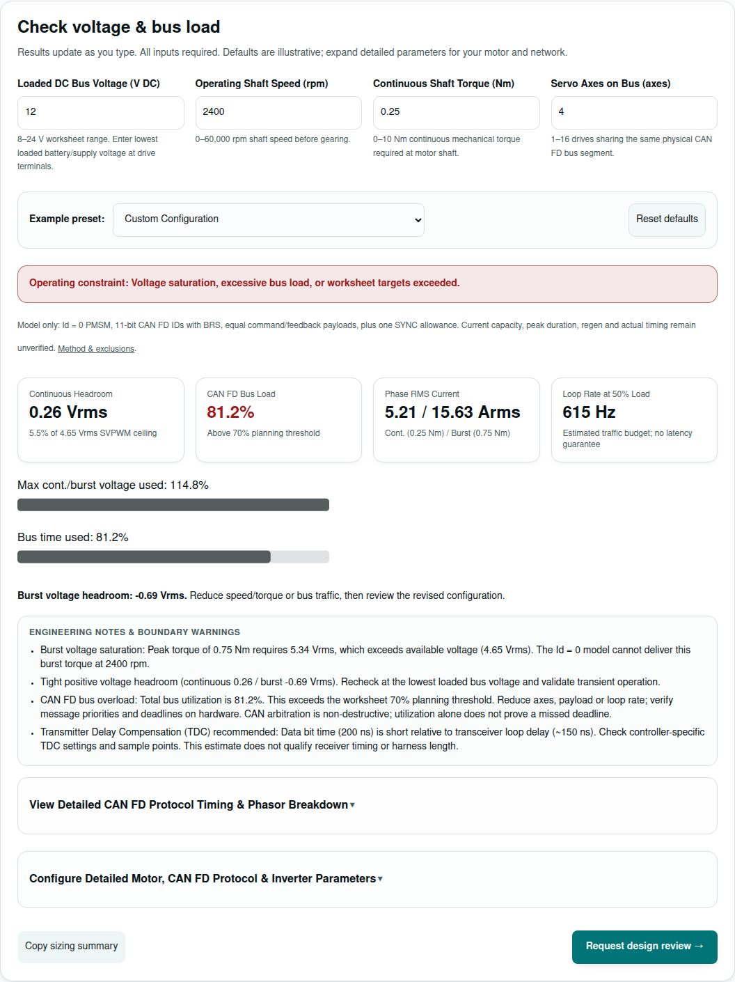
Check voltage & bus load
Results update as you type. All inputs required. Defaults are illustrative; expand detailed parameters for your motor and network.
8–24 V worksheet range. Enter lowest loaded battery/supply voltage at drive terminals.
0–60,000 rpm shaft speed before gearing.
0–10 Nm continuous mechanical torque required at motor shaft.
1–16 drives sharing the same physical CAN FD bus segment.
Model only: Id = 0 PMSM, 11-bit CAN FD IDs with BRS, equal command/feedback payloads, plus one SYNC allowance. Current capacity, peak duration, regen and actual timing remain unverified. Method & exclusions.
Burst voltage headroom: -0.69 Vrms. Reduce speed/torque or bus traffic, then review the revised configuration.
Engineering Notes & Boundary Warnings
- Burst voltage saturation: Peak torque of 0.75 Nm requires 5.34 Vrms, which exceeds available voltage (4.65 Vrms). The Id = 0 model cannot deliver this burst torque at 2400 rpm.
- Tight positive voltage headroom (continuous 0.26 / burst -0.69 Vrms). Recheck at the lowest loaded bus voltage and validate transient operation.
- CAN FD bus overload: Total bus utilization is 81.2%. This exceeds the worksheet 70% planning threshold. Reduce axes, payload or loop rate; verify message priorities and deadlines on hardware. CAN arbitration is non-destructive; utilization alone does not prove a missed deadline.
- Transmitter Delay Compensation (TDC) recommended: Data bit time (200 ns) is short relative to transceiver loop delay (~150 ns). Check controller-specific TDC settings and sample points. This estimate does not qualify receiver timing or harness length.
View Detailed CAN FD Protocol Timing & Phasor Breakdown▼
Protocol & Physical Layer Details
Electrical Phasor & Inverter Loss
Configure Detailed Motor, CAN FD Protocol & Inverter Parameters▼
Motor Constants & PWM Switching
0–25 Nm acceleration or shock torque (must be >= continuous).
0.005–2.0 Nm/Arms sinusoidal phase RMS torque constant.
Line-line RMS BEMF constant. A >15% mismatch flags review; smaller mismatch does not verify measurement convention.
Phase resistance at elevated operating temperature (typically 1.25–1.35x cold resistance).
2–5,000 µH equivalent phase-to-neutral inductance (half terminal-to-terminal for balanced Y).
Integer pole pairs (e.g. 7 for 14-pole robotic actuator).
20–100 kHz worksheet range. Higher frequency reduces the ripple proxy but can increase switching loss; verify actual devices.
CAN FD Physical Layer & Cycle Rate
Nominal arbitration rate (typically 500 kbps or 1000 kbps) for ID arbitration and ACK.
Accelerated data rate (typically 2000 kbps or 5000 kbps) during payload transmission.
100–4,000 Hz cyclic synchronous communication frequency (e.g. 1 kHz for 1 ms loop).
8–64 whole application bytes per message, per direction. Rounded up to a CAN FD wire length (8/12/16/20/24/32/48/64 bytes).
0.2–30 m total bus length end-to-end between the two 120 Ω termination resistors.
Thermal & Cooling Configuration
Chassis cold-plate bracket (Rth=4.5 C/W) vs still air enclosure (Rth=14 C/W).
Internal robot enclosure or ambient temperature around the drive heat spreader.
Decision summary: separate voltage, traffic and hardware gates
| Gate | Decision | Basis / limit |
|---|---|---|
| Motor voltage | Check continuous and burst headroom at lowest loaded bus voltage. | TI SPRA524 — space-vector PWM (1999); Vbus/√6 phase RMS with a worksheet 5% reserve. |
| Network capacity | Reduce payload, axes or cycle rate when estimated traffic exceeds the planning target. | Bosch — CAN FD protocol overview; worksheet timing assumptions are disclosed in Method. |
| Application compatibility | Request the exact firmware profile and supported motion modes before ordering. | CiA 402 series — drives and motion control |
| Physical link | Evaluate bit timing and test the actual harness. SIC can improve ringing behavior. | CiA 601 series — CAN FD design guidelines; NXP TJA1463 datasheet, revision 3.0 (2025). |
| Regeneration | Verify an energy sink under full charge, disconnect and deceleration conditions. | Energy conservation calculation below; component limits are project specific. |
1. Motor voltage and current: use consistent RMS conventions
The worksheet assumes a balanced sinusoidal PMSM with Id = 0. Enter phase-to-neutral resistance and inductance, line-to-line RMS Ke, and torque per phase RMS ampere. Available phase voltage is Vbus/√6 × 0.95, or 4.65 Vrms at 12V. The 5% reserve is an assumption; field weakening and magnetic saturation are excluded. TI SPRA524 — space-vector PWM (1999).
| Speed | Electrical frequency | Required phase voltage | Continuous headroom |
|---|---|---|---|
| 1000 rpm | 116.7 Hz | 2.03 Vrms | 2.63 Vrms |
| 1800 rpm | 210.0 Hz | 3.38 Vrms | 1.27 Vrms |
| 2400 rpm | 280.0 Hz | 4.40 Vrms | 0.26 Vrms |
| 3000 rpm | 350.0 Hz | 5.41 Vrms | -0.76 Vrms |
Sweep assumptions: Kt 0.048 Nm/Arms; Ke 2.90 Vrms L-L/krpm; hot Rph 0.065 Ω; Lph 65 µH; 7 pole pairs. Inductive voltage drop is proportional to speed and current; the phasor magnitude combines it with back-EMF and resistance.
2. CAN FD bandwidth: budget both directions and synchronization
CAN FD provides up to 64 payload bytes and can switch data rate within a frame. Bosch — CAN FD protocol overview. This tool assumes one equal-sized command and feedback message per axis per cycle, plus one nominal-rate SYNC allowance. A larger PDO can reduce application fragmentation while taking longer on the bus.
| Wire payload / direction | Estimated FD frame time | 4-axis load incl. SYNC | Axes at ≤50% estimate |
|---|---|---|---|
| 8 bytes | 50.0 µs | 46.0% | 4 axis/axes |
| 16 bytes | 64.4 µs | 57.5% | 3 axis/axes |
| 32 bytes | 94.0 µs | 81.2% | 2 axis/axes |
| 48 bytes | 122.8 µs | 104.2% | 1 axis/axes |
| 64 bytes | 151.4 µs | 127.1% | 1 axis/axes |
Wire lengths above 8 bytes are discrete: 12, 16, 20, 24, 32, 48 and 64. Entered application lengths are padded up before timing. See Bosch M_CAN user manual, revision 3.3.1 (2023). The 50% planning target reserves time; priority and response-time analysis remain necessary even below it.
3. Application protocol: CAN FD alone is insufficient
Ask whether the drive uses CANopen FD, a proprietary CAN FD protocol, or another application layer. A CAN FD transceiver does not establish drive-profile or firmware compatibility. The control word, status word and supported operating modes must match the master. CiA 402 series — drives and motion control.
| Option | Potential benefit | Cost / mismatch to resolve |
|---|---|---|
| CAN FD application protocol | Compact differential bus with flexible payload size | Master integration, message mapping and synchronization are firmware dependent. |
| Classical CANopen | Existing master and drive ecosystem | Up to 8 bytes per frame; budget fragmentation and actual cycle time. |
| EtherCAT | Candidate when a project needs its timing and motion ecosystem | Evaluate controller, topology, software and connector requirements against actual product specifications. |
4. Bit timing and the physical harness
Clock tolerance cannot be selected from bitrate alone. Evaluate the controller clock, prescaler, segments, SJW, sample points, oscillator drift and transceiver delay together. TDC helps the transmitter sample its own delayed signal; it does not repair receiver timing or arbitrary cable length. CiA 601 series — CAN FD design guidelines; Bosch M_CAN user manual, revision 3.3.1 (2023).
Terminate the trunk at both physical ends, typically with 120 Ω differential termination for a matching cable, and keep stubs short. TI SLLA270 — CAN physical layer requirements (2008). The tool’s 0.3 m / 0.6 m stub values are starting heuristics, not ISO limits. Test topology, connector capacitance, temperature and flexing. NXP describes SIC as reducing ringing; it does not bridge slip-ring contact interruptions. NXP TJA1463 datasheet, revision 3.0 (2025).
5. Regeneration: an energy sink must fit the actual duty cycle
First-principles example, separate from the interactive calculator: ΔEcap = ½C(Vmax² − Vstart²). A 470 µF bank rising from 12 to 15.5V stores only 0.0226 J. A hypothetical inertia of 8 × 10⁻⁵ kg·m² at 2,500 rpm stores ½Jω² = 2.74 J. Neither the voltage threshold nor inertia is a product specification.
| Item | Calculated value | Decision / limit |
|---|---|---|
| Resistance ceiling for 150W absorption | R ≤ V²/P = 1.40 Ω | At full duty, 1.5 Ω absorbs only 140.2W and cannot meet this assumed peak. |
| Illustrative 1.2 Ω branch | I = 12.08A; P = 175.2W at 14.5V | Validate switch current, safe operating area, tolerances, fuse and control response. |
| Assumed 2.74 J pulse every 2s | 1.37W average at assumed 100% transfer; not a resistor rating | Pulse energy and transient temperature govern separately from continuous wattage. |
| Battery / bidirectional supply alternative | Unknown until sink limits are provided | Check charge acceptance, BMS opening, reverse blocking and wiring drop. |
A continuous “50W” resistor label alone does not qualify this pulse. Obtain its pulse-energy curve and repetition derating. The worksheet cannot predict a universal time to overvoltage or certify a braking circuit.
6. PWM, thermal loss and EMI: separate proxies from ratings
The ripple estimate ΔIpp ≈ Vbus/(4fswLph) is a screening proxy. Increasing PWM frequency reduces this proxy but can increase switching losses. Example bridge assumptions are 4 mΩ vs 8 mΩ, 8 ns vs 30 ns combined switching transitions and 0.6W auxiliary loss. These compare assumed devices; they do not prove a technology-wide efficiency advantage.
Common-mode current follows I = C × dv/dt. For a hypothetical 12V transition over 5 ns, dv/dt = 2.4 V/ns; 1.5 pF couples 3.6 mA. Measure real overshoot and transition time before selecting isolation, choke or split termination. Component parasitics and a poor return path can worsen signal quality; adding a generic choke is not automatic qualification.
7. Hybrid power and data cable: mechanical savings need electrical checks
A combined cable may reduce connector count, but no mass saving or current rating is assumed. Preserve a controlled-impedance CAN pair and an appropriate signal reference or isolation scheme. Size the separate power conductors for DC supply current, round-trip voltage drop, flex life, bundling and temperature rise.
| Unknown | Risk | Minimum evidence / alternative |
|---|---|---|
| Drive voltage range and current duty | Undervoltage, overvoltage or overheating | Exact part datasheet; reduce torque/speed or change drive. |
| Regeneration sink | Bus rise when source refuses energy | Measured profile plus sink specification; add absorption or lengthen deceleration. |
| Harness and rotating contacts | Dropouts and receiver timing errors | Harness drawing, error counters and environmental tests; lower data rate or revise topology. |
| Thermal interface | Estimated junction proxy misses hot spots | Mounted thermal test; improve cooling or derate current. |
| Protocol/firmware support | A correct electrical link cannot command motion | Master/drive interoperability and fault-recovery tests. |
| Integration cost | Custom mapping, connectors and EMC retests add work | Prototype BOM and test scope; compare an existing supported interface. |
8. Reproducible application scenarios
These are illustrative software scenarios using the tool’s presets, not customer deployments or measured hardware results. Presets intentionally include review and constraint outcomes; an application label does not assert feasibility. Select the same preset above to reproduce both continuous and burst constraints. A positive continuous margin can coexist with a burst or bus constraint.
| Scenario / assumptions | Continuous / burst headroom | Estimated bus load | Screening outcome |
|---|---|---|---|
| Quadruped Robot Leg Actuator (4 Axes, 1 kHz CSP, 5 Mbps CAN FD) — 12V; 2200 rpm; 32 bytes/direction | 0.64 / -0.78 Vrms | 81.2% incl. SYNC | CONSTRAINT: reduce speed/torque or change winding; reduce traffic and verify deadlines |
| Collaborative Arm Wrist / Gripper (2 Axes, 500 Hz, 2 Mbps CAN FD) — 12V; 1800 rpm; 64 bytes/direction | 1.62 / 0.80 Vrms | 69.7% incl. SYNC | REVIEW: reduce traffic and verify deadlines |
| AMR / AGV Dual Wheel Traction (2 Axes, 250 Hz, 2 Mbps CAN FD) — 11.5V; 650 rpm; 32 bytes/direction | -0.12 / -2.85 Vrms | 25.0% incl. SYNC | CONSTRAINT: reduce speed/torque or change winding; validate hardware and scheduling |
| Stress Test: High Speed + 12 Axes @ 2 kHz (Demonstrates Constraints) — 12V; 5500 rpm; 48 bytes/direction | -6.72 / -8.38 Vrms | 1269.6% incl. SYNC | CONSTRAINT: reduce speed/torque or change winding; reduce traffic and verify deadlines |
9. Calculation method and exclusions
Motor: I = torque/Kt; fe = rpm × pole pairs/60; Eb = Ke × rpm/1000/√3; Vreq = √[(Eb + RI)² + (2πfeLI)²]; Vavailable = Vbus/√6 × 0.95. Fundamental phase RMS values; motor saliency, acceleration dynamics and field weakening are excluded.
Traffic estimate: round payload to a supported DLC length B. Use 30 nominal-rate bits and D = 6 + 8B + ceil(8B × 0.12) + C data-rate bits, with C = 22 for B ≤16 or 27 otherwise. Tframe = 1000 × (30/arb_kbps + D/data_kbps) µs. Tbusy = 2N × Tframe + 60000/arb_kbps µs, including one 60-bit nominal-rate SYNC allowance. Load% = Tbusy × loop_Hz/10000; rate at 50% = floor(500000/Tbusy).
Timing limitations: the fixed fields and 12% stuffing allowance approximate frame timing; this is not a bit-exact encoder or a worst-case bound. CRC-region constants are lumped allowances, not exact fixed-stuff or stuff-count encoding. Extended IDs, actual SYNC payload, diagnostics, errors/retransmissions, arbitration blocking and host/drive latency are excluded. Use actual frame traces and response-time analysis for acceptance.
Loss proxy: Iripple,rms = ΔIpp/(2√3); Irms = √(Icont² + Iripple,rms²); Pcond = 3Irms²R; Psw = 1.5VbusIcontfsw(tr+tf), with an extra assumed 25 nC recovery term for the silicon example. Temperature proxy = ambient + total assumed loss × assumed thermal resistance. Motor heat and detailed device losses are excluded.
Results: “within targets” means only that the stated worksheet thresholds were not exceeded. Kt/Ke convention mismatch, large ripple and tight voltage margins trigger review. The 15% Kt/Ke mismatch flag is illustrative and does not verify the convention below that threshold. Current capacity, peak duration, regen, clock tolerance, compliance and safety remain unqualified.
10. Questions before selecting a 12V CAN FD servo drive
Scope
Is this a product selector or a qualified drive rating?
It is a preliminary worksheet. It does not check a specific part number, peak-current duration, firmware profile, functional safety, or regenerative absorption. Confirm these against the proposed module datasheet.
Does the calculator size the brake resistor?
No. Braking is a separate worked example below. The interactive outputs cover motor voltage/current, estimated CAN FD traffic, and illustrative inverter loss.
Motor
Which voltage should I enter for a nominal 12V battery?
Use the lowest loaded voltage measured at the drive terminals. Battery state of charge, temperature, connector resistance and cable drop can reduce the available phase voltage. Also verify the maximum charged and regenerated voltage separately.
Are phase RMS current and battery current interchangeable?
No. This tool reports sinusoidal phase RMS current from torque/Kt. DC supply current depends on mechanical power, copper loss, inverter loss and speed. Harness current must be assessed separately.
What motor conventions does the worksheet require?
Kt must be Nm per phase Arms, Ke line-to-line RMS V per krpm, and R/L phase-to-neutral. The model assumes a balanced sinusoidal PMSM, Id = 0, with no field weakening, saturation or saliency. Confirm manufacturer conventions before using the result.
Network
Does CAN FD support imply CANopen FD or CiA 402 compatibility?
No. CAN FD describes the data link. Confirm the application protocol, supported drive profile revision, motion modes, object dictionary, PDO mapping, SYNC behavior and firmware on both master and drive.
Why does entering 33 payload bytes consume 48 wire bytes?
CAN FD DLC encoding uses discrete lengths above eight bytes. This worksheet rounds application data up to the next supported wire length and uses that padded length for timing.
Does a bus load below 50% guarantee a motion deadline?
No. The 50% target and 70% warning threshold are worksheet planning assumptions. Identifier priorities, release times, blocking, arbitration, bit stuffing, retries, host latency and drive execution must be analyzed and measured.
Is a quartz oscillator of 50 ppm mandatory at 5 Mbps?
There is no universal tolerance value derived from bitrate alone. Evaluate controller clock, prescaler, segment lengths, SJW, sample points, drift and transceiver asymmetry together using the controller documentation and a timing tool.
Does SIC repair a worn slip ring or allow arbitrary stubs?
No. SIC reduces topology-related ringing. It cannot bridge contact interruptions. Qualify the complete harness, rotating contacts, node capacitance and temperature range at the selected bit timing.
Power & EMI
Does every 12V servo system require a brake chopper?
It requires a verified energy absorption path. A receptive battery or bidirectional supply may absorb regeneration within its limits. If it cannot, consider a suitably rated chopper, shared sink or reduced deceleration. Include BMS disconnect and full-charge behavior.
Can AWG20 power wires always carry 15A?
No. Current capacity and voltage drop depend on conductor material, length, insulation, bundling, ambient temperature, flex duty and connector derating. Select from the actual cable and connector datasheets and test temperature rise.
Does higher PWM frequency eliminate motor heating?
The ripple proxy decreases with switching frequency, but switching and gate-drive losses can rise. Choose frequency from measured motor ripple, temperature and EMI; a semiconductor technology label alone cannot establish efficiency.
Integration
What should I send for an engineering review?
Copy the tool summary and provide the motor datasheet, torque duty cycle, minimum and maximum bus voltage, regeneration profile, master/drive firmware, message IDs, harness drawing and cooling conditions. Review scope and timing are confirmed after these are available.
11. Sources, review date and evidence boundaries
First recorded 2026-11-08 · Reviewed · GaN Servo Drives. Public primary sources checked 2026-11-08. Older documents are identified by revision and used within the scope below. Next content review: by 2027-05-08, or earlier if controller, protocol or model assumptions change. All worked examples are disclosed assumptions and calculations. No customer, medical, aerospace or production qualification evidence is supplied for this page.
- Bosch — CAN FD protocol overview
Protocol context: switched data rate and up to 64 payload bytes. Does not certify this worksheet timing estimate.
- Bosch M_CAN user manual, revision 3.3.1 (2023)
Sections 2.4.3 (printed p. 51) and 3.1.4 (pp. 60–61): DLC encoding and local transmitter delay compensation. Controller settings remain device specific; TDC does not compensate end-to-end cable delay.
- CiA 601 series — CAN FD design guidelines
Physical interface, bit timing, clock tolerance evaluation and signal improvement. Public overview; restricted full specifications were not used to infer universal numeric limits.
- NXP TJA1463 datasheet, revision 3.0 (2025)
SIC operation and device-specific electrical/timing conditions. Reference transceiver only; no claim that a GSD drive contains this part.
- CiA 402 series — drives and motion control
Drive state machine, control/status words and process-data mapping. Firmware profile and supported modes require confirmation.
- TI SPRA524 — space-vector PWM (1999)
Space-vector modulation background. Phase RMS conversion and the 5% worksheet reserve are explicitly stated model choices.
- TI SLLA270 — CAN physical layer requirements (2008)
Termination, grounding and propagation background for classical CAN. This older report does not establish a universal 5 Mbps harness limit.
12. Next step: confirm a module and a validation plan
For selection context, review our servo drive product families, application integration guides and OEM development scope. These are enquiry routes; exact 12V ratings and CAN FD firmware remain subject to confirmation.
Copy your worksheet summary, attach the motor datasheet, torque/speed duty profile, supply and sink limits, firmware details, message schedule, harness drawing and cooling conditions. Ask for the exact drive part number and supported protocol; review timing and scope depend on the supplied information.
Related checks: 12V BLDC motor matching · 12V board-level integration · module and firmware confirmation.