

Dual Absolute Encoder Integration in High-Speed GaN Servo Drives: BiSS-C & SSI Signal Integrity, Dual-Loop FOC Latency, and Mechanical Compliance
Dual absolute encoder integration in GaN servo drives: compare BiSS-C and SSI, budget feedback delay, and use an RFQ checklist to qualify your drive supplier.
Dual absolute encoder integration in GaN servo drives measures both motor angle and load position. For a geared robot joint, use the motor encoder for Field-Oriented Control (FOC) commutation and velocity feedback, and the output encoder for position correction. This helps compensate for transmission error and compliance that a motor encoder cannot directly observe. Whether two absolute encoders are necessary depends on startup position requirements, permissible load error, and the transmission mechanics.
Gallium Nitride (GaN) stages enable compact, fast-switching inverters, but the actual PWM frequency and switching-node slew rate depend on voltage, gate drive, load, and layout. Closely packed power stages and encoder readheads can couple displacement currents into differential clock and data lines. The 50 V/ns example below is an assumed interference scenario, not a measured specification for every low-voltage GaN drive.
This guide compares BiSS-C and SSI selection considerations, models noise coupling and feedback delay, compares magnetic and optical sensing rings, and provides an RFQ checklist. EnDat 2.2 is an alternative requiring its own compatible master and encoder documentation; its implementation is outside this guide.
Executive Selection Summary:
- Topology allocation: Use motor feedback for commutation/velocity and load feedback for position. The illustrative update rates are 50–100 kHz current, 10–20 kHz velocity, and 1–2 kHz position; update rate is not closed-loop bandwidth or a product guarantee.
- Interface ratings: Check bus-pin common-mode range separately from an isolation barrier's Common-Mode Transient Immunity (CMTI). Isolation does not make bus pins immune to excessive voltage relative to their local ground.
- Clock and cable: Qualify the complete master, encoder, transceivers, and harness together. Line-delay compensation helps sampling alignment but cannot repair a degraded data eye.
- Error handling: Specify maximum stale-position age, diagnostic coverage, and a validated fault response. There is no universal safe number of corrupted frames to ignore.
- Transducer trade-offs: Compare installed accuracy, contamination tolerance, magnetic immunity, and thermal drift; resolution alone does not establish accuracy.
Published and reviewed: November 1, 2026. Scope: Global, English-language technical selection and procurement guide. The focus is low-voltage (24V–60V DC) integrated robotic joint actuators and compact decentralized servo drives. Numerical design examples are assumptions for screening, not manufacturer ratings or safety certification.
Method and limitations: The timing calculations, displacement current models, and control bandwidth figures below are derived from fundamental transmission line and motion control equations. They serve as comparative design tools for engineering specification rather than guaranteed bench measurements of a specific GaN Servo Drives part number. Always verify exact component datasheets, PCB layer stackups, and mechanical tolerances with your actuator hardware partner prior to volume freeze.
For production actuator designs, review the Driver + Encoder Integrated Servo Board and the Robot Joint Servo Drive specifications to evaluate mechanical dimensions and supported feedback protocols.
1. The Electromechanical Imperative for Dual Encoders
In conventional industrial automation, servo drives utilize a single encoder mounted at the non-drive end of the motor shaft. The controller calculates joint output position by dividing the motor rotor angle by the gear reduction ratio N:
θ_output_calc = θ_motor / N
While mechanically straightforward, this assumption breaks down in precision collaborative robots, humanoid articulating limbs, surgical manipulators, and high-payload automated guided vehicle (AGV) steering pivots.
K_θ). Values are example assumptions, not product ratings. Scroll horizontally on small screens.1.1 Reducer Compliance, Hysteresis, and Transmission Error
Strain wave gears and miniature cycloidal drives offer compact reduction, but low advertised backlash does not establish zero loaded positioning error. Evaluate these effects against the selected reducer's documentation:
-
Torsional Elasticity (
K_θ): A harmonic drive relies on a flexible steel cup (flexspline) that elastically deforms as the elliptical wave generator rotates. Under external gravitational or acceleration torques (τ_load), the flexspline twists:Δθ_torsion = τ_load / K_θ(τ)For nonlinear stiffness, use the measured torque-angle curve rather than one constant. A motor-side encoder cannot directly observe output deflection.
-
Kinematic Transmission Error (TE): Tooth profile and assembly errors create periodic angle errors; obtain the specified and measured error for the selected reducer.
-
Lost Motion and Hysteresis: Friction and structural deflection create direction-dependent error. Request reversal measurements under representative torque.
-
Thermal Expansion Drift: Bearing, housing, and scale expansion can shift alignment and the zero datum. Check the intended temperature range.
1.2 Impact on Robotic Tool Center Point (TCP)
In a 6-axis or 7-axis robotic arm with a 1.0-meter reach, an uncompensated angular deflection of 0.2° at joint 1 or joint 2 translates to a Tool Center Point position error:
ΔX_TCP ≈ L × sin(Δθ) ≈ 1000 mm × sin(0.2°) ≈ 3.49 mm
This illustrative single-joint estimate can exceed a precision assembly error budget; full-arm TCP error also depends on pose, calibration, and structural flexure. Load-side feedback can reduce the observable joint error within the control bandwidth, but cannot remove all compliance or guarantee sensor-limited TCP accuracy. Maxon's dual-loop guide explains the motor/load feedback roles and the need for tuning.
2. High-Speed GaN Switching (dV/dt) vs. Differential Encoder Signal Integrity
While dual encoders solve the mechanical compliance problem, implementing them in compact GaN-based actuators introduces an electromagnetic signal integrity challenge.
2.1 Capacitive Displacement Current Generation
For an assumed 48 V transition lasting 2 ns, the average slew rate is:
dV/dt = 48V / 2ns = 24 V/ns = 24,000 V/µs
The separate 50 V/ns interference scenario below assumes a faster edge. Measure switching-node slew rate on the actual assembly; bus voltage and PWM frequency alone do not determine it.
Any parasitic capacitance (C_parasitic) between the high-voltage switching node, motor phase conductors, or ground reference planes and the low-voltage encoder signal lines conducts a transient displacement current:
I_disp = C_parasitic × dV/dt
Consider a hollow-shaft joint assembly where motor phase leads run parallel to an encoder flex PCB or unshielded harness for just 30 mm, introducing an estimated parasitic coupling capacitance of 5 pF:
I_disp = 5 × 10⁻¹² F × 50 × 10⁹ V/s = 0.25 A = 250 mA
The calculated 250 mA is instantaneous current through the assumed coupling capacitance, not measured differential receiver current. The return path, coupling symmetry, and protection network determine how much becomes differential error.
2.2 Common-Mode Slew Rate vs Transceiver Operating Boundaries
RS-422 and RS-485 have different common-mode requirements: ±7 V for RS-422, and −7 V to +12 V for RS-485, as summarized in Analog Devices AN-960. Check the actual receiver's input threshold, operating range, and absolute maximum ratings.
Ground movement and unequal coupling can move a receiver outside its operating range, producing false transitions or frame errors. Measure both differential and common-mode waveforms at the receiver. A CMTI rating describes an isolation barrier under specified test conditions; it is not an extended bus-pin common-mode rating.
2.3 Physical Layer Transceiver Architecture Comparison
Table 1 is an architecture screening matrix, not a component benchmark. Obtain datasheet limits and worst-case measurements for each candidate.
| RFQ question | Non-isolated differential interface | Integrated isolated interface | Digital isolator + separate transceiver |
|---|---|---|---|
| Reference relationship | Shared signal reference required | Separate logic and bus references | Separate references across barrier |
| Bus-pin common-mode range | Check receiver datasheet | Still limited relative to bus-side ground | Set by transceiver, not isolator |
| Barrier CMTI | Not applicable: no isolation barrier | Verify guaranteed minimum at temperature | Verify isolator minimum and direction/channel count |
| Propagation delay | Budget driver, cable, receiver | Include internal isolation delay and skew | Sum isolator and transceiver delays |
| Power supply | Local encoder/interface supply | Check whether isolated power is included | Budget isolated power where required |
| Maximum usable clock | Limited by complete link timing and eye | Include barrier pulse-width distortion | Include both devices' timing limits |
| Layout requirement | Continuous return path and controlled pair routing | Preserve barrier separation and bus return | Preserve separation across both signal and power paths |
| Acceptance evidence | Error counters and waveforms under load | Same tests plus barrier transient conditions | Same tests plus channel skew and power behavior |
Choose isolation where reference movement, installation, or electrical separation requirements justify it. A cable through a hinge does not by itself establish a universal CMTI threshold. Specialized BiSS Line hardware is a different physical layer and is not a drop-in substitute for an RS-422 BiSS-C master.
3. Protocol Architecture & Timing: BiSS-C vs. SSI
Absolute encoders communicate position words through synchronous digital serial protocols. In dual-encoder robotics, the drive acts as the Master, generating a clock signal (MA) that commands one or more encoder Slaves to stream back serialized data bits (SLO).
3.1 BiSS-C Protocol Anatomy and Error Mechanisms
BiSS-C is an open standard. Follow the BiSS C Protocol Description, Rev D2, particularly the frame, line-delay, and cycle-time sections:
- Idle and header: The header contains ACK, start, and Control Data Slave (
CDS); the latch event is the first rising clock edge at the slave. - Data channel: Position length, status bits, and CRC parameters depend on the encoder profile. A common encoder configuration uses active-low error/warning bits and inverted CRC-6 with polynomial
x⁶ + x + 1(0x43). - Timeout: Static or adaptive timeout resets the frame. Its duration affects the minimum interval between fresh samples.
Do not configure the master from nominal position resolution alone: obtain the complete frame definition, CRC settings, processing time, and minimum cycle time.
3.2 Cable Length vs Clock Frequency Limits
In distributed drive architectures, signal propagation delay across the transmission cable alters the phase relationship between the clock edge sent by the master and the data bit received from the slave.
The round-trip propagation delay (t_round_trip) is:
t_round_trip = 2 × L_cable × d_prop + t_electronics
Here d_prop = 5 ns/m is an assumed one-way delay per unit length (equivalent to a propagation speed of about 2 × 10⁸ m/s), and t_electronics = 25 ns is an illustrative combined driver/receiver response budget.
Table 2 applies a simplified uncompensated half-cycle sampling model with t_setup = 15 ns: f_ceiling = 1 / (2 × (t_round_trip + t_setup)). These calculated ceilings exclude attenuation, jitter, and device frequency limits; they are not qualified operating clocks.
| Cable length | Assumed cable round trip | Total round-trip delay | Calculated sampling ceiling | Required next check |
|---|---|---|---|---|
| 0.3 m | 3 ns | 28 ns | 11.63 MHz | Apply encoder/master clock limit |
| 1.0 m | 10 ns | 35 ns | 10.00 MHz | Measure data eye and jitter margin |
| 3.0 m | 30 ns | 55 ns | 7.14 MHz | Validate phase alignment on harness |
| 5.0 m | 50 ns | 75 ns | 5.56 MHz | Check attenuation and connector effects |
| 10.0 m | 100 ns | 125 ns | 3.57 MHz | Qualify compensation range and eye |
| 20.0 m | 200 ns | 225 ns | 2.08 MHz | Test worst-case cable and temperature |
BiSS-C delay compensation adjusts sampling alignment; it does not create a universal clock-versus-length guarantee. SSI implementations may offer master-side sampling adjustment, but basic SSI does not standardize BiSS-C's line-delay mechanism. Require the supplier's tested master/encoder/cable combination.
4. Dual-Loop Cascade Architecture & FOC Latency Budget
In a compliant geared system, load feedback introduces mechanical dynamics that can limit control bandwidth. The cascade below is a common starting point; stability depends on the measured plant and controller design.
4.1 Functional Allocation: Inner vs. Outer Loops
The control architecture must be partitioned into two distinct cascades:
- FOC commutation and current loop: Motor electrical angle comes from ENC 1 or a validated rotor estimator; current feedback comes from current sensors. A 50–100 kHz update rate is an example execution target, not a requirement to obtain a fresh serial position every cycle.
- Inner velocity loop: ENC 1 senses motor motion without the reducer between the rotor and sensor. An example 10–20 kHz execution rate must be distinguished from the much lower achievable closed-loop bandwidth.
- Outer position loop: ENC 2 measures output position. An example 1–2 kHz execution rate leaves bandwidth to be chosen from measured compliance, inertia, and frequency response. Tune any notch or low-pass filter from that response; filtering adds phase delay.
4.2 End-to-End Latency Budget
For a pure delay t_delay, the phase-lag magnitude at frequency f is:
φ_lag = 360° × f × t_delay
Evaluate this at the intended gain-crossover frequency, not the software update rate. For a loop executing at 10 kHz with a 1 kHz crossover, an assumed 25 µs feedback delay adds 360° × 1,000 × 25 × 10⁻⁶ = 9°. It does not establish stability by itself.
Table 3 is an illustrative allocation at a 10 MHz clock, not measured drive performance. The serialized lengths include data/status/CRC; the separate header/processing allowance must be replaced with the encoder's actual worst-case timing. Channels are assumed to run concurrently.
| Timing Stage | Inner Motor Encoder (ENC 1) | Outer Load Encoder (ENC 2) | Engineering Mechanism / Constraint |
|---|---|---|---|
| 1. Sampling Trigger to Latch | 0.05 µs | 0.05 µs | Hardware timer event aligned to PWM center |
| 2. Header / Sensor Processing Allowance | 0.50 µs | 0.50 µs | Assumed overhead; replace from datasheet |
| 3. Data / Status / CRC Transmission | 3.20 µs (32 bits @ 10 MHz) | 3.60 µs (36 bits @ 10 MHz) | Serialized bits divided by clock frequency |
| 4. Cable & Transceiver Delay | 0.04 µs (0.5 m harness) | 0.12 µs (1.5 m harness) | 2 × L × d_prop + t_electronics; different channel electronics assumed |
| 5. Hardware CRC Verification | 0.10 µs | 0.10 µs | Assumed non-overlapped processing |
| 6. Position Unwrapping & Scaling | 0.25 µs | 0.35 µs | Assumed fixed-point processing |
| 7. Allocated Feedback Delay | 4.14 µs | 4.72 µs | Sum of the above allocations |
| Delay Lag at 1 kHz Crossover | 1.49° | 1.70° | Pure-delay contribution only |
| Delay Lag at 100 Hz Crossover | 0.15° | 0.17° | Pure-delay contribution only |
This allocation excludes digital filter delay, regulator scheduling, PWM output delay, and any unreported internal sensor latency. Timeout also limits fresh-sample cadence: an assumed 10 µs timeout plus 3.2 µs data transfer already exceeds a 10 µs current-loop period before other overhead. A 100 kHz current loop may therefore require a different encoder timing configuration or validated angle prediction between fresh samples. Synchronizing requests to PWM reduces scheduling jitter, but cable skew and internal sensor sampling delay still require measurement.
5. Sensor Transducer Comparison: Off-Axis Magnetic vs. Optical Rings
In hollow-shaft actuators, wiring or cooling channels may pass through the joint center. Hollow-bore ring encoders preserve that passage, although the motor-side sensor may use another location if the mechanical envelope permits. Two candidate technologies are multi-pole magnetic rings and grating-scale optical rings.
5.1 Environmental and Electromechanical Trade-Offs
Table 4 identifies qualification questions. Installed performance depends on the selected scale, readhead, mounting, and calibration; it cannot be inferred from sensing technology alone.
| Performance Metric | Off-Axis Magnetic Encoder (TMR / Hall) | Precision Optical Encoder (Reflective Grating) |
|---|---|---|
| Resolution | Obtain native/interpolated counts and noise | Obtain counts and interpolation settings |
| Installed accuracy | Request full-revolution error with actual magnet and mounting | Request scale/readhead accuracy including eccentricity |
| Repeatability | Test approach direction, speed, and temperature | Test the same conditions; do not substitute resolution |
| Airgap and runout | Use supplier gap, tilt, and eccentricity limits | Use supplier optical alignment and runout limits |
| Dust, oil, and grease | Often tolerant of nonmagnetic contamination; check debris and sealing | Verify allowable scale contamination and enclosure design |
| Motor/brake magnetic fields | Validate stray-field tolerance under maximum current | Optical sensing avoids magnetic angle coupling; electronics remain EMI-sensitive |
| Thermal behavior | Test magnet strength, carrier expansion, and sensor drift | Test scale/carrier expansion and readhead alignment |
| Shock and vibration | Qualify the complete ring and adhesive/mounting system | Qualify scale material, mounting, and readhead assembly |
| Cost and sourcing | Quote sensor, ring, calibration, shielding, and yield | Quote scale, readhead, alignment, sealing, and yield |
5.2 Magnetic Crosstalk from Motor Windings and Holding Brakes
In Hollow Shaft Integrated Joints, test magnetic encoder angle error while varying phase current, rotor angle, and holding-brake state. The acceptable stray field depends on the sensor and magnet geometry; there is no universal 0.5 mT failure threshold.
Differential sensing can reject spatially uniform fields, but gradients, saturation, and imbalance leave residual error. Evaluate sensor placement and any high-permeability shielding with the assembled joint; shield thickness and material must be chosen for the actual flux and mechanical constraints.
6. PCB Layout, Shielding, and Interconnect Engineering
Reduce coupling at its source and qualify encoder error rates under representative switching conditions. A finite test with zero observed CRC errors does not prove an error-free interface in every installation.
6.1 PCB Stackup Partitioning
In a 6-layer or 8-layer circular joint board:
- Layer 1 (Top): Low-voltage digital logic, MCU, BiSS-C transceivers, and encoder readheads.
- Layer 2 (Ground Plane): Solid, unbroken Digital Ground (DGND) plane directly beneath the transceivers and signal traces.
- Layer 3 (Power Bus): Logic supply rails (+3.3V, +5V, +12V auxiliary).
- Layer 4 & 5 (Internal Ground & Power): High-current DC bus (+48V) and Power Ground (PGND).
- Layer 6 (Bottom): GaN HEMTs, phase output copper, and gate drive loops.
Routing rule: Keep encoder pairs over a continuous local reference, away from switching-node copper. The layer allocation above is illustrative: minimize commutation-loop area and preserve the intended return paths. Derive spacing from coupling, voltage, stackup, and applicable insulation requirements; 3 mm is not a universal signal-integrity or safety clearance.
6.2 Differential Termination and Common-Mode Filtering
- Differential termination: Match termination to cable impedance at the receiving end:
MAat the encoder andSLOat the master. A 120 Ω cable suggests 120 Ω termination, subject to driver loading limits. Validate any split/AC network rather than prescribing one capacitor for every link. - Common-mode filtering: Evaluate chokes only where measurements justify them. Check differential insertion loss, resonance, skew, and transient behavior at the chosen clock rate; filtering can degrade the data eye.
- Shield connection: Where the enclosure/EMC plan calls for it, use a low-inductance 360° shield-to-chassis connection. A pigtail adds impedance: for an assumed 10–30 nH,
X_L = 2πfLgives about 6–19 Ω at 100 MHz, not an open circuit. Coordinate chassis bonding and signal reference with the installation grounding plan.
7. Sourcing Strategy and RFQ Procurement Checklist
When sourcing integrated servo drives, off-the-shelf catalog claims of "BiSS-C / SSI Supported" are insufficient to ensure reliable dual-loop joint operation. Sourcing managers and systems engineers should mandate the following technical criteria in their Request for Quotation (RFQ).
7.1 Engineering & Sourcing Verification Matrix
Compare candidate suppliers against the following 9-point verification checklist:
- 1. Two feedback paths: Obtain channel topology, latch skew, timestamps, and worst-case sample age. Separate masters or a supported chain may be acceptable if the timing requirements are met.
- 2. Electrical limits: Request exact transceiver/isolator part numbers, bus-pin common-mode limits, and barrier CMTI where isolation is used, across the specified temperature range.
- 3. Clock and cable qualification: Require the tested encoder/master/harness combination, delay-compensation capability, cable length, clock rate, and waveform/error-counter evidence.
- 4. Bounded fault response: Define CRC/status/timeout handling, maximum stale-data age, divergence limits, and fault-injection results. Set stop or fallback behavior from the application's risk assessment.
- 5. Execution and fresh-data timing: Obtain worst-case current, velocity, and position execution times, actual sensor refresh rates, filter delays, and any prediction method; compare them with the application deadlines.
- 6. Compliance tuning: Require frequency-response evidence over the payload/inertia range, filter settings and delay, and stability margins for the intended controller configuration.
- 7. Magnetic Shielding & Decoupling Data: If onboard magnetic sensing is used, supplier must provide bench test reports demonstrating angular accuracy under full-load motor phase current (stray field immunity verification).
- 8. Thermal validation: Request readhead, scale/magnet, and PCB temperatures at worst-case load/ambient, plus angle drift and calibration limits. Qualify thermal separation without compromising mounting or electrical return paths.
- 9. Supply Continuity & Alternate Qualification: Sourcing agreement must specify primary and secondary qualified part numbers for encoder interface ICs, microcontrollers, and transceivers, with mandatory revision notification for any silicon or firmware changes.
For custom mechanical envelopes or specialized hollow-bore diameters, initiate an OEM Custom Solutions review with your physical drawing and joint torque requirements.
8. Frequently Asked Questions
Can a GaN servo drive achieve dual-loop control using a single encoder?
The motor/load feedback architecture described here needs measurements at two mechanical locations. A single motor encoder cannot directly observe reducer deflection at the output. Other systems may combine one encoder with an estimator or direct-drive mechanics; those require separate validation and do not provide the same independent load-position measurement.
What is the functional difference between BiSS-C and SSI in high-speed GaN drives?
Basic SSI does not standardize a common CRC or BiSS-C's line-delay mechanism; some encoder variants add parity/status bits and masters can add plausibility checks. BiSS-C offers protected data channels and register communication, but CRC configuration is profile-specific. For procurement, verify the exact frame, diagnostics, timing, and master compatibility. Protocol choice alone does not establish functional safety or immunity to GaN switching noise.
Why does BiSS-C report CRC errors during motor acceleration, but not at rest?
Acceleration changes current, modulation, supply loading, and mechanical cable stress. Correlate error counters with receiver waveforms, encoder supply voltage, grounding, and motion. Switching edges can remain fast at standstill, so acceleration-only faults do not uniquely diagnose shielding, chokes, or CMTI. Test both motor and load channels over current, speed, braking, and temperature.
How does line delay auto-compensation work in BiSS-C?
The master uses ACK response timing to align its sampling of the returning data. This compensates for line delay within the master's supported range. Sensor processing time, pulse distortion, jitter, and attenuation remain separate constraints; verify the selected encoder's timing and the received data eye.
Can optical encoders be integrated directly onto the GaN inverter PCB?
Potentially, if temperature, alignment, vibration, contamination, and electrical noise remain within the chosen readhead/scale limits. A separate carrier or thermally separated PCB region may help, but the mounting must retain stiffness and alignment. Validate the assembled joint rather than inferring readhead temperature from transistor junction ratings.
What happens if the secondary (load) encoder fails during operation?
A well-architected dual-loop drive implements an active sensor divergence monitor:
|θ_motor / N − θ_load − θ_offset| ≤ θ_threshold
Apply consistent units, direction, multi-turn unwrapping, and sample timestamps before this comparison. The threshold must accommodate expected compliance and dynamic lag. A load-encoder failure may require a controlled stop, a validated degraded mode, or another response defined by the machine risk assessment. Motor-only fallback is not automatically safe, and brake sequencing depends on the mechanism. Require documented fault-injection tests and fieldbus fault reporting.
9. Next Steps for Engineering and Procurement
Dual feedback can improve loaded positioning when sensor accuracy, signal integrity, timing, and mechanical dynamics meet the application budget. It does not eliminate physical compliance or guarantee sub-millimeter TCP accuracy. Use the RFQ checklist to obtain evidence before committing to a drive or actuator design.
To evaluate dual-encoder hardware for your upcoming joint actuator or machine revision:
- Review the Driver + Encoder Integrated Servo Board for hollow-bore dimensions and protocol specifications.
- Examine the 48V Servo Driver Board and EtherCAT 48V Servo Drive for decentralized multi-axis architectures.
- For custom humanoid joint envelopes or multi-turn battery-backed configurations, consult the OEM Custom Engineering Team to review your mechanical envelope, gear compliance curves, and fieldbus requirements.
Sources and References
Checked November 1, 2026. These primary sources support the protocol, physical-layer, and control-architecture explanations. Numerical allocations and screening tables in this article are explicitly illustrative, not test results from these sources or ratings for a GaN Servo Drives product.
- BiSS Association — BiSS C Protocol Description, Rev D2: Frame/header, line delay, latch point, processing time, and minimum cycle-time calculation; see printed pages 6–10 and 27.
- Analog Devices — AN-960: RS-485/RS-422 Circuit Implementation Guide: Common-mode ranges and termination placement. This is physical-layer guidance, not GaN-specific qualification.
- maxon — EPOS4: Dual loop control: Motor/load encoder roles, gear configuration, and frequency-response-based tuning. Product-specific examples do not establish another drive's capabilities.
- Texas Instruments — Interface to a 5-V BiSS Position Encoder, TIDA-00175 / TIDU410: Reference interface hardware and test methodology. Its stated conditions must not be generalized into a universal CMTI or cable-length guarantee.
Author

More Posts
Evaluating Monolithic 3-Phase GaN Servo Micromodules: 2026 Procurement & Engineering Guide
A 2026 engineering and procurement guide to monolithic 3-phase GaN servo micromodules, thermal limits, supplier risk, sourcing checklist, and fit for compact robotics.

Frameless Motor Integration: Sourcing Guide for Hollow Shaft Servo Drives
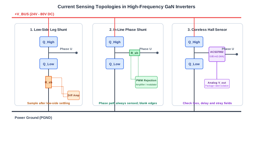
Current Sensing Architectures in High-Speed GaN Servo Drives: In-Line Phase Current vs Low-Side Shunts vs Coreless Magnetic Sensors
Compare current sensing in GaN servo drives: low-side shunts, in-line shunts and magnetic sensors. Use timing and thermal examples plus an RFQ checklist to select.